


ASUS CUWE User’s Manual 41
3. HARDWARE SETUP
Connectors
3. H/W SETUP
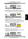
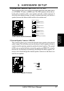
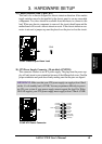
23) Chassis Intrusion Lead (2-pin CHA)
This lead is for a chassis designed for chassis intrusion detection. After-market
toggle switches may also be installed to the chassis panel or on any removable
components. Two wires should be available from the chassis to connect to this
lead. When any chassis component is removed, the circuit should open and the
motherboard will record a chassis intrusion event. If the chassis intrusion con-
nector is not used, a jumper cap must be placed over the pins to close the circuit.
010101
®
CUWE
CUWE Chassis Open Alarm Lead
CHA
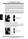
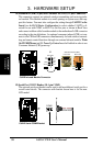
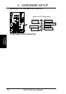
24) ATX Power Supply Connector (20-pin block ATXPWR)
This connector connects to an ATX power supply. The plug from the power sup-
ply will only insert in one orientation because of the different hole sizes. Find the
proper orientation and push down firmly making sure that the pins are aligned.
IMPORTANT: Make sure that your ATX power supply can supply at least 10mA
on the +5-volt standby lead (+5VSB). You may experience difficulty in power-
ing ON your system if your power supply cannot support the load. For Wake-
On-LAN support, your ATX power supply must supply at least 720mA +5VSB.
010101
®
CUWE
CUWE ATX Power Connector
+3.3Volts
-12.0Volts
Ground
Power Supply On
Ground
Ground
Ground
-5.0 Volts
+5.0 Volts
+5.0 Volts
Power Good
+12.0Volts
+3.3 Volts
+3.3 Volts
Ground
+5.0 Volts
Ground
+5.0 Volts
Ground
+5V Standby