


14
ASUS A7N266-E User’s Manual
3. HARDWARE SETUP
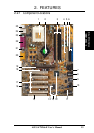
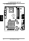
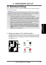
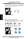
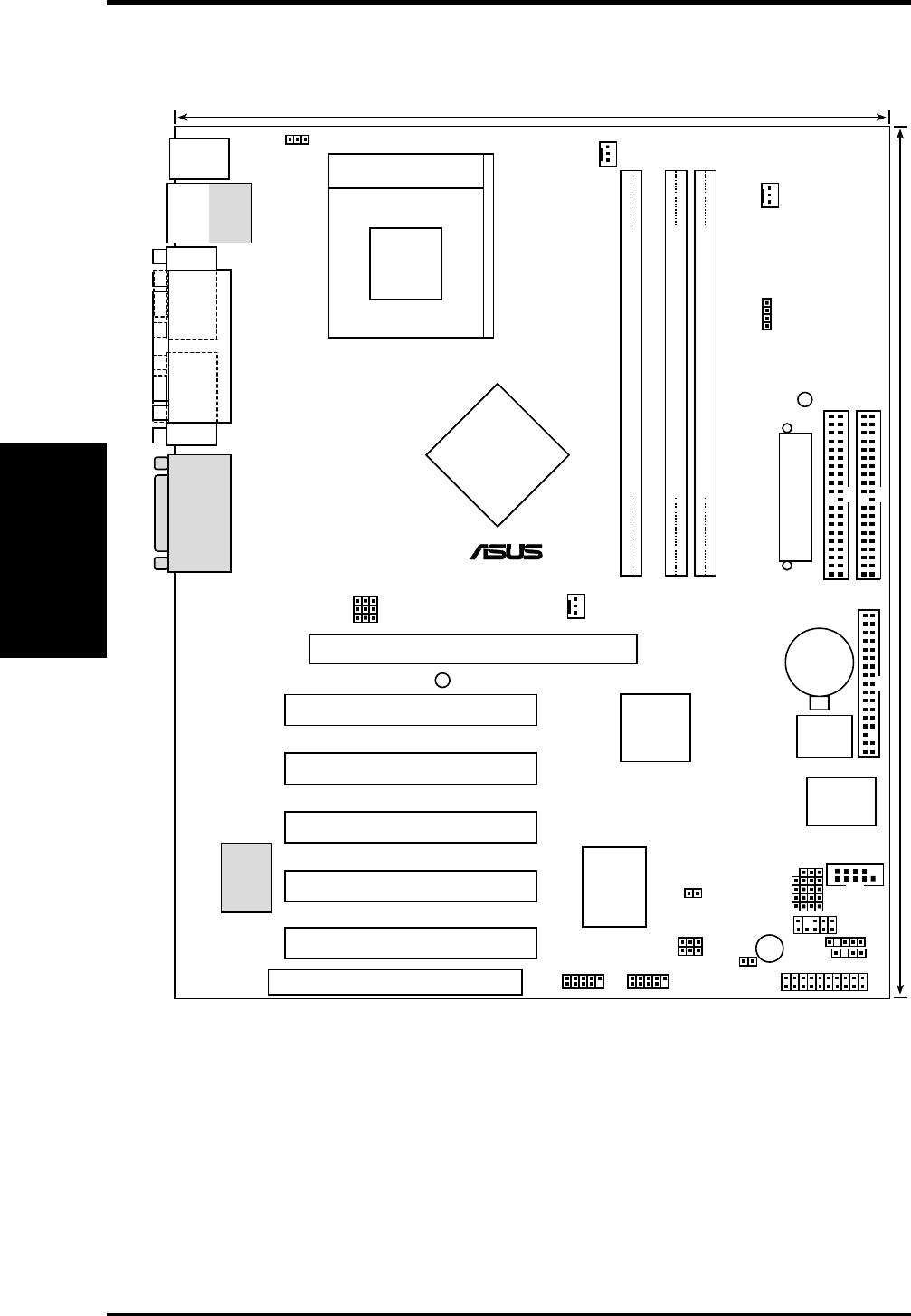
3.1 Motherboard Layout
Motherboard Layout
3. H/W SETUP
IR
24.5cm (9.64in)
30.5cm (12.0in)
Primary IDE
Secondary IDE
FLOPPY
A7N266-E
nVidia
MCP-D
Chipset
ASUS
ASIC
with Hardware
Monitor
Accelerated Graphics Port (AGP Pro)
nVidia
nForce
IGP-128
Chipset
CR2032 3V
Lithium Cell
CMOS Power
PLED
01
DDR DIMM1 (64/72 bit, 184-pin module)
0 1
01
DDR DIMM2 (64/72 bit, 184-pin module)
2 3
ATX Power Connector
ACR
Super
I/O
2Mb
BIOS
01
DDR DIMM2 (64/72 bit, 184-pin module)
4 5
®
Socket 462
PCI 1
PCI 2
PCI 3
PCI 4
PCI 5
PS/2
T: Mouse
B: Keyboard
RJ-45
Top:
USB1
USB2
Bottom:
COM1
PARALLEL PORT
VGA
GAME_AUDIO
Realtek
RTL8100
COM2
VDDR
PANEL
USB45 USB23
JTPWR
USBPWR01
SMB
CHASSIS
BUZZER
IDELED
USBPWR23
USBPWR45
CLRTC
BSEL0
CPU_FAN
CHA_FAN
NB_FAN
VID1
VID2
VID3
VID4
BSEL1
WARNING
JEN
(Grayed components are optional at the time of purchase.)