


22 ASUS A7N266-E User’s Manual
3. HARDWARE SETUP
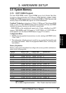
System Memory
3. H/W SETUP
A7N266-E
010101
®
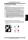
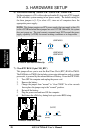
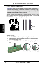
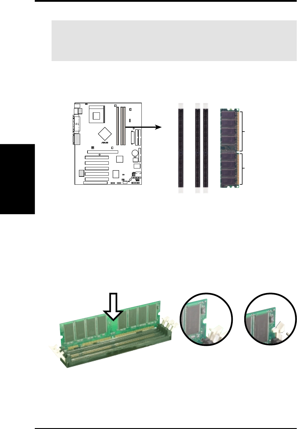
A7N266-E 184-Pin DDR
DIMM Sockets
80 Pins
104 Pins
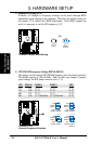
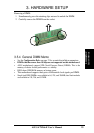
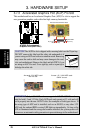
3.5.2 Memory Installation
WARNING! Make sure that you unplug your power supply when adding or
removing memory modules or other system components. Failure to do so may
cause severe damage to both your motherboard and expansion cards (see 3.3
Hardware Setup Procedure for more information).
Insert the module(s) as shown. Because the number of pins are different on either
side of the breaks, the module will only fit in the orientation shown. A 184-pin DDR
DRAM DIMM has a single notch slightly to the right of center.
Installing a DIMM:
1. Unlock a DIMM socket by pressing the retaining clips outward.
2. Align a DIMM on the socket such that the notches on the DIMM exactly
match the notches in the socket.
3. Firmly insert the DIMM into the socket until the retaining clips snap back in
place.
Unlocked Retaining Clip Locked Retaining Clip