


40 ASUS A7N266-E User’s Manual
3. HARDWARE SETUP
Connectors
3. H/W SETUP
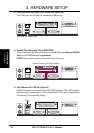
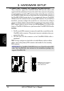
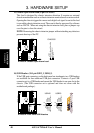
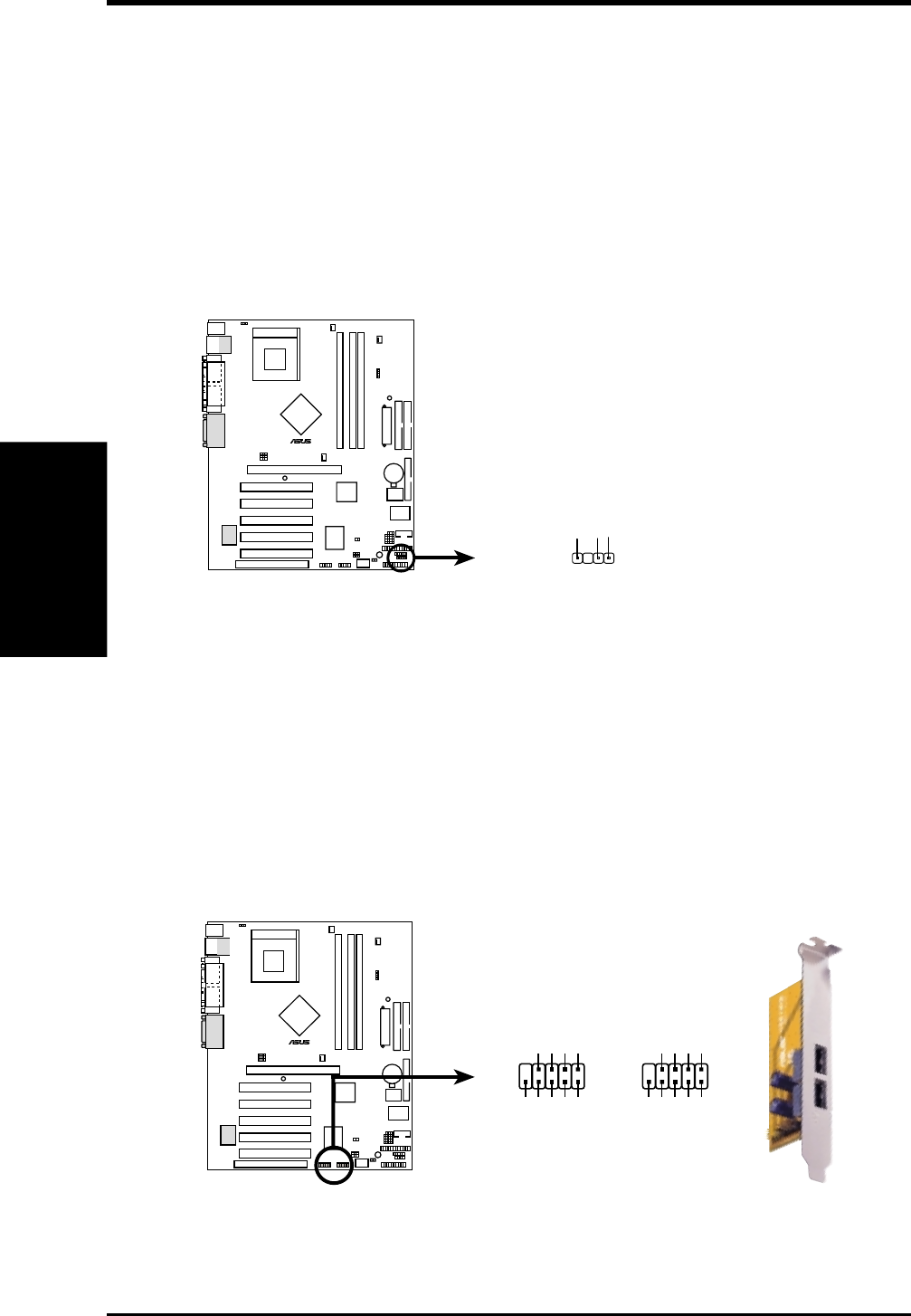
15) Chassis Open Alarm Lead (4-pin CHASSIS)
This lead is designed for chassis intrusion detection. It requires an external
detection mechanism such as a chassis intrusion monitor/sensor or microswitch.
Opening the chassis triggers the sensor and a high-level signal is sent to this lead
to record the chassis intrusion event. The event is then be processed by software
such as LDCM. When not using the chassis intrusion lead, place a jumper cap
over the pins to close the circuit.
NOTE: Removing the chassis intrusion jumper without attaching any detectors
prevents boot-up of the PC.
A7N266-E
010101
®
A7N266-E Chassis Open Alarm Lead
CHASSIS
+5Volt
(Power Supply Stand By)
Ground
Chassis Signal
1
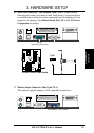
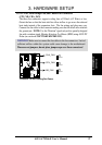
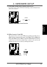
16) USB Headers (10-1 pin USB2_3, USB4_5)
If the USB port connectors on the back panel are inadequate, two USB headers
are available for four additional USB port connectors. Connect a 2-port USB
connector set to a USB header and mount the USB bracket to an open slot in the
chassis. (The USB connector set is optional and does not come with the
motherboard package.)
A7N266-E
010101
®
A7N266-E Front Panel USB Headers
USB23USB45
NC
GND
USBP4+
USBP4–
USB Power
GND
USBP5+
USBP5–
USB Power
15
610
15
610
NC
GND
USBP2+
USBP2–
USB Power
GND
USBP3+
USBP3–
USB Power