


ASUS A7V266-C User’s Manual 35
3. HARDWARE SETUP
Connectors
3. H/W SETUP
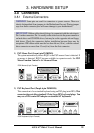
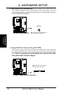
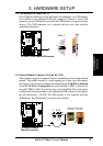
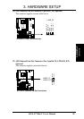
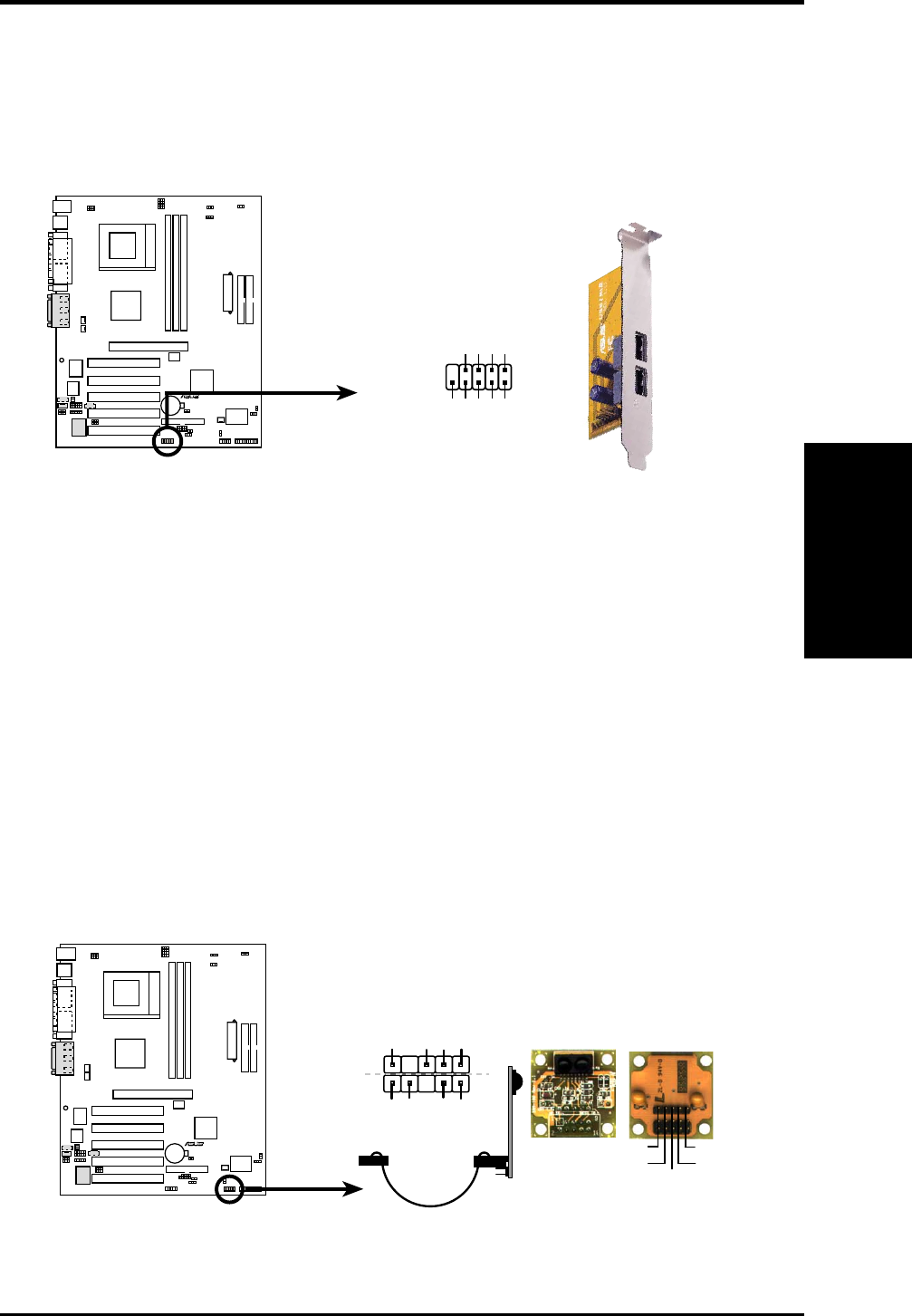
12) USB Headers (10-1 pin USB2_3)
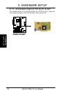
If the USB port connectors on the back panel are inadequate, two USB headers
are available for two additional USB port connectors. Connect a 2-port USB
connector set to a USB header and mount the USB bracket to an open slot in the
chassis. (The USB connector set is optional and does not come with the
motherboard package.)
R
A7V266-C
A7V266-C Front Panel USB Headers
USB Power
USBP2–
USBP2+
GND
NC
USB Power
USBP3–
USBP3+
GND
15
610
USB2_3
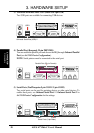
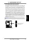
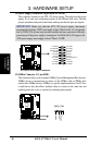
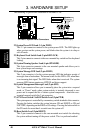
13) Infrared Module Connector (10-2 pin IR_CON)
This connector supports an optional wireless transmitting and receiving infrared
module. This module mounts to a small opening on system cases that support
this feature. You must also configure the setting through UART2 Use Infrared
(see 4.4.2 I/O Device Configuration) to select whether UART2 is directed for
use with COM2 or IrDA. Use the five pins as shown in Back View and connect
a ribbon cable from the module to the motherboard SIR connector according to
the pin definitions. (NOTE: The SIR module is not supplied with the
motherboard. The CIR module is currently not available.)
R
A7V266-C
A7V266-C Infrared
Module Connector
Standard Infrared (SIR)
Front View Back View
+5V
IRTX
IRRX
(NC)
GND
SIR
+5V
IRRX
IRTX
GND
IRAX
GND
CIRRX
CIR+5V
CIR