


ASUS A7V8X-MX SE motherboard user guide
1-17
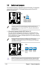
1.12 Connectors
This section describes and illustrates the connectors on the motherboard.
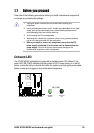
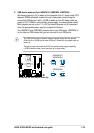
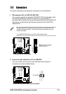
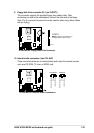
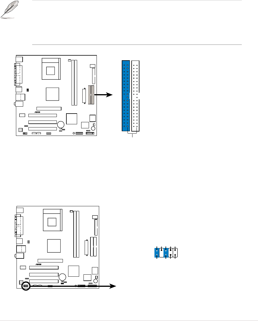
1. IDE connectors (40-1 pin PRI_IDE, SEC_IDE)
This connector supports the provided UltraATA133 IDE hard disk ribbon cable.
Connect the cable’s blue connector to the primary (recommended) or
secondary IDE connector, then connect the gray connector to the UltraATA133
slave device (hard disk drive) and the black connector to the UltraATA133
master device.
Pin 20 on each IDE connector is removed to match the covered hole on the
UltraATA133 cable connector. This prevents incorrect orientation when you
connect the cables.
For UltraATA133 IDE devices, use 40-pin 80-conductor cable.
A7V8X-MX SE
®
A7V8X-MX SE IDE Connectors
NOTE: Orient the red markings
(usually zigzag) on the IDE
ribbon cable to PIN 1.
SEC_IDE
PRI_IDE
PIN 1
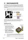
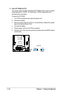
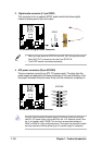
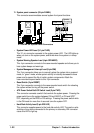
2. Front panel audio connectors (10-1 pin FPAUDIO)
This is an interface for front panel audio cable that allows convenient
connection and control of audio devices.
A7V8X-MX SE
®
A7V8X-MX SE Front Panel Audio Connector
FP_AUDIO
BLINE_OUT_L
MIC2
Line out_R
Line out_L
BLINE_OUT_R
NC
MICPWR
+5VA
AGND