


ASUS A7VL-VM User’s Manual 29
3. HARDWARE SETUP
Connectors
3. H/W SETUP
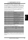
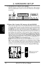
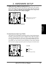
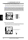
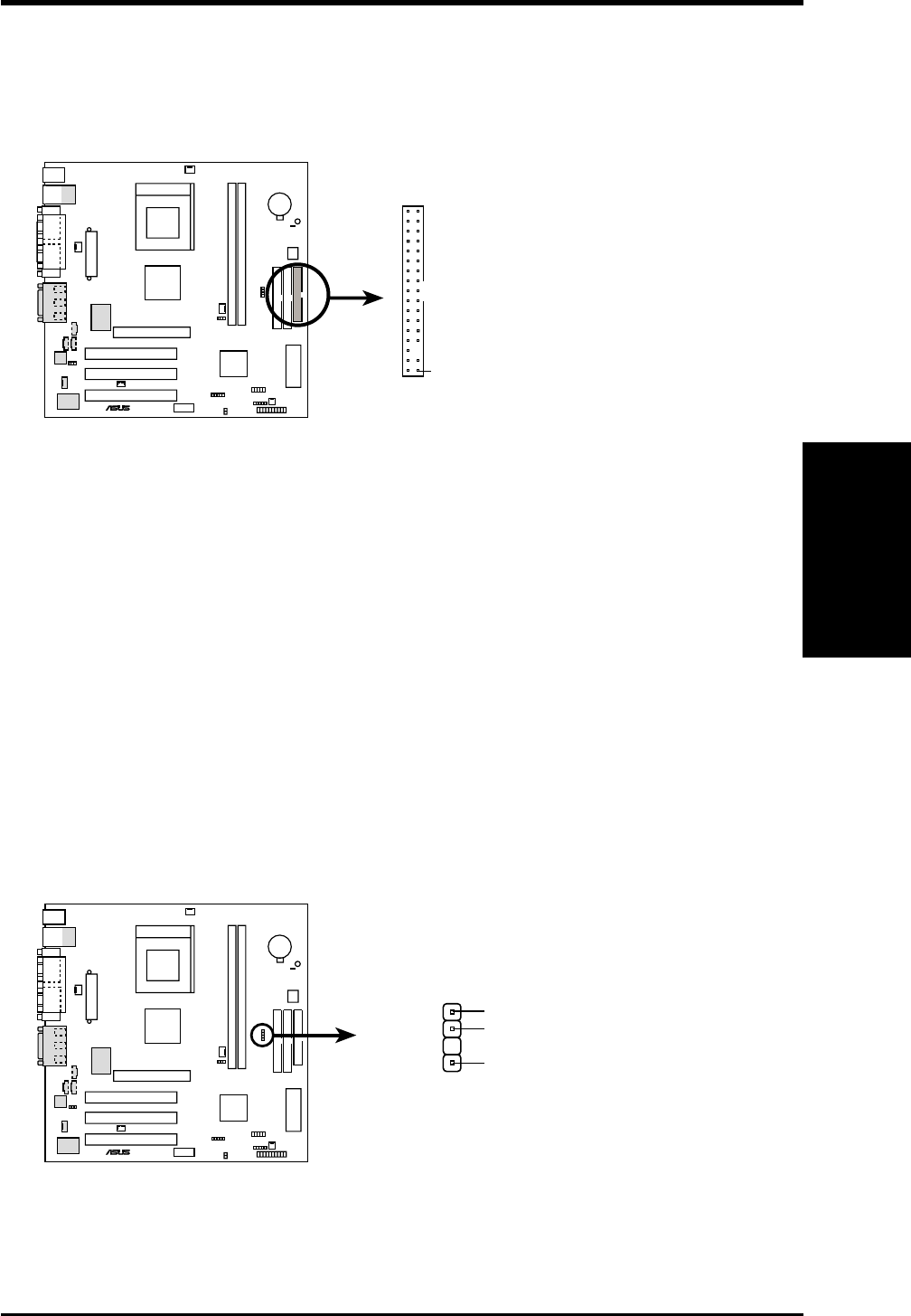
12) Chassis Intrusion Lead (4-1 pin CHASS)
This requires an external detection mechanism such as a chassis intrusion moni-
tor/sensor or microswitch. The sensor is triggered when a high level signal is
sent to the Chassis Signal lead, which occurs when a panel switch or light detec-
tor is triggered. This function works with an optional ASUS CIDB chassis intru-
sion module (see your vendor for more information). If the chassis intrusion
lead is not used, a jumper cap must be placed over the pins to close the circuit.
1
+5Volt
(Power Supply Stand By)
Ground
Chassis Signal
A7VL-VM Chassis Open Alarm Lead
CHASSIS
A7VL-VM
®
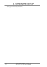
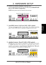
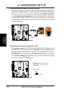
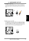
11) Floppy Disk Drive Connector (34-1 pin FLOPPY)
This connector supports the provided floppy drive ribbon cable. After connect-
ing the single end to the board, connect the two plugs on the other end to the
floppy drives. (Pin 5 is removed to prevent inserting in the wrong orienta-
tion when using ribbon cables with pin 5 plugged).
NOTE: Orient the red markings on
the floppy ribbon cable to
PIN 1
A7VL-VM Floppy Disk Drive Connector
PIN 1
A7VL-VM
®