


ASUS A7VL-VM User’s Manual 31
3. HARDWARE SETUP
Connectors
3. H/W SETUP
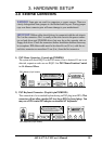
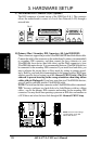
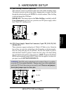
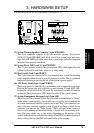
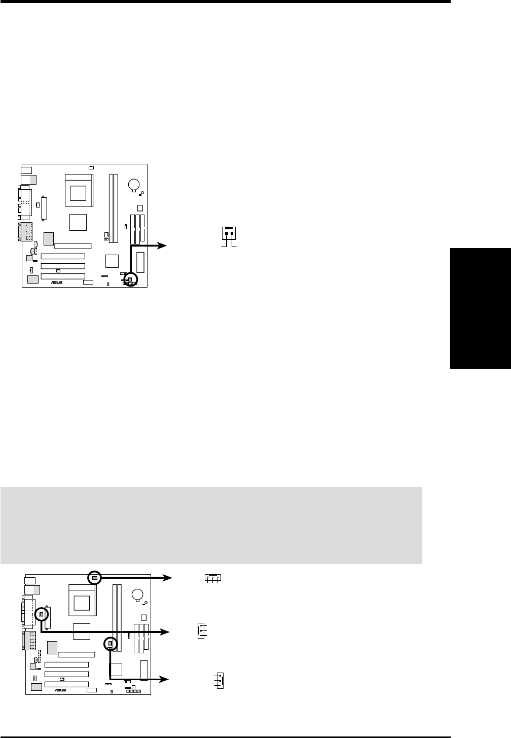
16) CPU, Power Supply, Chassis Fan Connectors (3-pin CPU_FAN, PS_FAN,
CHASS_FAN)
These connectors support cooling fans of 350mA (4.2 Watts) or less. Orient the
fans to blow air across the onboard heat sink. Depending on the fan manufac-
turer, the wiring and plug may be different. The red wire should be positive,
while the black should be ground. Connect the fan’s plug to the board taking
into consideration the polarity of the connector. NOTE: Rotations Per Minute
(RPM) can be monitored using ASUS PC Probe if the fan supplies a rotation out-
put signal. (see 6. SOFTWARE REFERENCE).
WARNING! The CPU and/or motherboard will overheat if there is no airflow
across the CPU and onboard heatsinks. Damage may occur to the motherboard
and/or the CPU fan if these pins are incorrectly used. These are not jumpers,
do not place jumper caps over these pins.
A7VL-VM
®
A7VL-VM 12-Volt Cooling Fan Power
CPU_FAN
PS_FAN
GND
Rotation
+12V
CHASS
GND
GND
+12V
GND
Rotation
+12V
_FAN
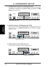
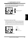
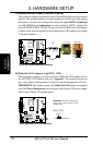
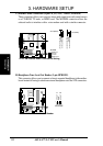
15) Wake-On-Ring Connector (2-pin WOR)
This connector connects to internal modem cards with a Wake-On-Ring output.
The connector powers up the system when a ringup packet or signal is received
through the internal modem card. NOTE: For external modems, Wake-On-Ring
is detected through the COM port.
IMPORTANT: This feature requires that Wake-On-Ring is enabled (see 4.4.3
Power Management) and that your system has an ATX power supply with at
least 720mA +5V standby power.
A7VL-VM
®
A7VL-VM Wake-On-Ring Connector
WOR
Ring#
Ground
2
1