


36 ASUS P3B-F User’s Manual
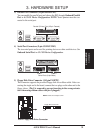
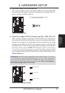
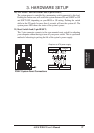
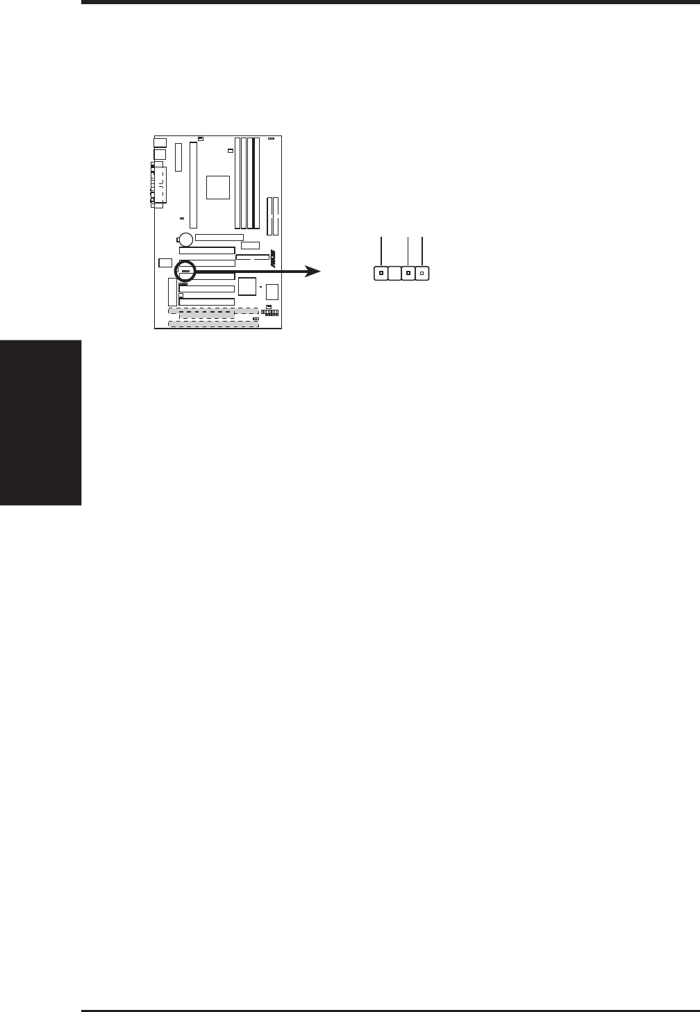
14) Chassis Intrusion Alarm Lead (4-1 pin CHASSIS)
This requires an external detection mechanism such as a chassis intrusion moni-
tor/sensor or microswitch. The sensor is triggered when a high level signal is
sent to the Chassis Signal lead, which occurs when a panel switch or light detec-
tor is triggered.
P3B-F Chassis Intrusion Alarm Lead
+5VSB
Chassis Signal
GND
CHASSIS
R
P3B-F
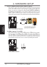
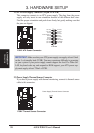
15) System Power LED Lead (3-1 pin PWR.LED)
This 3-1 pin connector connects to the system power LED, which lights when
the system is powered on, blinks when it is in sleep mode, and turns off when it
is in soft-off mode.
16) Keyboard Lock Switch Lead (2-pin KEYLOCK)
This 2-pin connector connects to the case-mounted key switch to allow keyboard
locking. NOTE: When the keyboard is locked, the mouse can still be used.
17) System Warning Speaker Connector (4-pin SPEAKER)
This 4-pin connector connects to the case-mounted speaker.
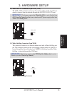
18) System Message LED Lead (2-pin MSG.LED)
This indicates whether a message has been received from a fax/modem. The
LED will remain lit when there is no signal and blink when there is data re-
ceived. This function requires an ACPI OS as well as application and driver
support.
19) System Management Interrupt Lead (2-pin SMI)
This allows the user to manually place the system into a suspend mode or “Green”
mode where system activity will be instantly decreased to save electricity and
expand the life of certain components when the system is not in use. This 2-pin
connector (see the preceding figure) connects to the case-mounted suspend
switch. If you do not have a switch for the connector, you may use the “Turbo
Switch” since it does not have a function. SMI is activated when it detects a
short to open moment and therefore leaving it shorted will not cause any prob-
lems. This may require one or two pushes depending on the position of the switch.
Connectors
3. H/W SETUP
3. HARDWARE SETUP