


ASUS P3B-F User’s Manual96
7. APPENDIX
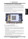
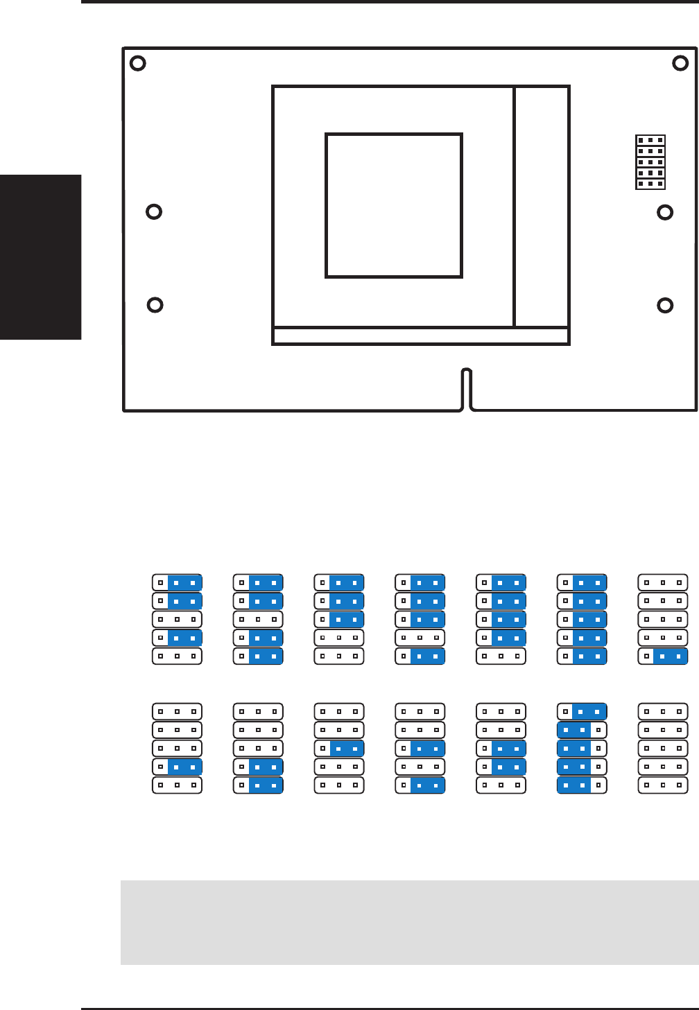
7.2.2 Setting up the ASUS S370 CPU transform card
Socket 370
JP1
JP2
JP3
JP4
JP5
CPU Voltage
Screw Hole
Screw Hole
Brown Lever
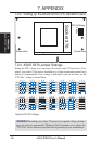
Socket 370 CPU Voltage
1.80Volts
123
JP5
JP4
JP2
JP1
JP3
1.85Volts
123
JP5
JP4
JP2
JP1
JP3
1.90Volts
123
JP5
JP4
JP2
JP1
JP3
1.95Volts
123
JP5
JP4
JP2
JP1
JP3
2.05Volts
123
JP5
JP4
JP2
JP1
JP3
2.00Volts
123
JP5
JP4
JP2
JP1
JP3
2.10Volts
123
JP5
JP4
JP2
JP1
JP3
2.20Volts
123
JP5
JP4
JP2
JP1
JP3
2.30Volts
123
JP5
JP4
JP2
JP1
JP3
2.40Volts
123
JP5
JP4
JP2
JP1
JP3
2.50Volts
123
JP5
JP4
JP2
JP1
JP3
CPU Def.
123
JP5
JP4
JP2
JP1
JP3
2.60Volts
123
JP5
JP4
JP2
JP1
JP3
Reserved
123
JP5
JP4
JP2
JP1
JP3
7.2.3 ASUS S370 Jumper Settings
Setting the CPU voltage is not necessary for current socket 370 processors. If re-
quired, your socket 370 processor should have its voltage requirement printed on its
surface or documentation. If no voltage is indicated or you are not sure, use the
“CPU Def.” setting as shown below.
WARNING! Exceeding your socket 370 processor’s required voltage can dam-
age your processor permanently! Make sure that the jumpers are as shown for
“CPU Def.” unless otherwise specified before powering on your motherboard.
7. APPENDIX
ASUS S370 CPU Card