


1-7ASUS V-Series M2V890
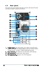
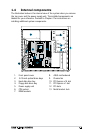
1.4 Internal components
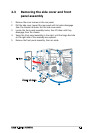
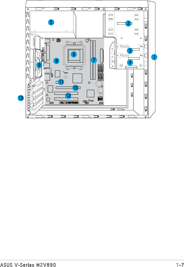
The illustration below is the internal view of the system when you remove
the top cover and the power supply unit. The installed components are
labeled for your reference. Proceed to Chapter 2 for instructions on
installing additional system components.
2
1
13
3
5
4
9
6
7
12
8
10
11
1. Front panel cover
2. 5.25-inch optical drive bays
3. Hard disk drive bay
4. Floppy disk drive bay
5. Power supply unit
6. CPU socket
7. DIMM sockets
8. ASUS motherboard
9. Chassis fan
10. PCI Express x16 slot
11. PCI Express x1 slot
12. PCI slots
13. Metal bracket lock