


ASUS H81I-PLUS
1-3
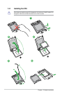
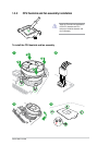
Unplug all power cables before installing the CPU.
• Upon purchase of the motherboard, ensure that the PnP cap is on the socket and
the socket contacts are not bent. Contact your retailer immediately if the PnP cap
is missing, or if you see any damage to the PnP cap/socket contacts/motherboard
components. ASUS will shoulder the cost of repair only if the damage is shipment/
transit-related.
• Keep the cap after installing the motherboard. ASUS will process Return Merchandise
Authorization (RMA) requests only if the motherboard comes with the cap on the
LGA1150 socket.
• The product warranty does not cover damage to the socket contacts resulting from
incorrect CPU installation/removal, or misplacement/loss/incorrect removal of the PnP
cap.
• Ensure that you install the correct CPU designed for LGA 1150 only. DO NOT install a
CPU designed for LGA1155 and LGA1156 sockets on the LGA1150 socket.
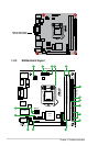
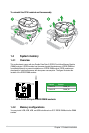
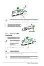
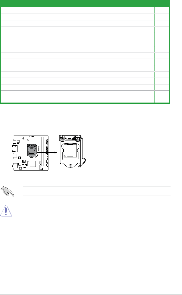
1.3 Central Processing Unit (CPU)
This motherboard comes with a surface mount LGA1150 socket designed for the Intel
®
4th
generation Core™ i7 / Core™ i5 / Core™ i3, Pentium
®
, Celeron
®
processors.
H81I-PLUS
H81I-PLUS CPU socket LGA1150
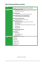
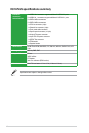
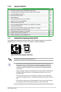
1.2.4 Layout contents
Connectors/Jumpers/Slots/LED Page
1. ATX power connectors (24-pin EATXPWR, 4-pin ATX12V) 1-15
2. CPU and chassis fan connectors (4-pin CPU_FAN, 4-pin CHA_FAN) 1-14
3. Clear RTC RAM (3-pin CLRTC) 1-10
4. Intel
®
LGA1150 CPU socket 1-3
5. DDR3 DIMM slots 1-6
6. System panel connector (10-1 pin F_PANEL) 1-17
7. Speaker connector (4-pin SPEAKER) 1-15
8. TPM connector (20-1 pin TPM) 1-18
9. Intel
®
H81 Serial ATA 3.0Gb/s connector (7-pin SATA3G_1~2 [brown]) 1-17
10. Onboard LED (SB_PWR) 1-18
11. Intel
®
H81 Serial ATA 6.0Gb/s connector (7-pin SATA6G_1~2 [yellow]) 1-14
12. Digital audio connector (4-1 pin SPDIF_OUT) 1-13
13. Front panel audio connector (10-1 pin AAFP) 1-13
14. USB 3.0 connector (20-1 pin USB3_12) 1-16
15. USB 2.0 connectors (10-1 pin USB910, 1112) 1-16