


ASUS H81I-PLUS
1-17
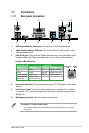
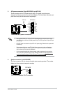
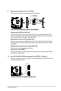
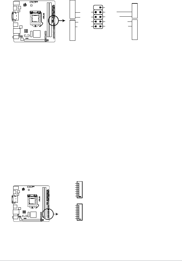
9. System panel connector (10-1 pin F_PANEL)
This connector supports several chassis-mounted functions.
H81I-PLUS
PIN 1
PWR BTN
GND
PWR
PLED-
PLED+
(NC)
Reset
Ground
HDD_LED-
HDD_LED+
F_PANEL
+PWR LED
+HDD_LED RESET
H81I-PLUS System panel connector
• System power LED (2-pin PWR_LED)
This 2-pin connector is for the system power LED. Connect the chassis power LED
cable to this connector. The system power LED lights up when you turn on the system
power, and blinks when the system is in sleep mode.
• Hard disk drive activity LED (2-pin HDD_LED)
This 2-pin connector is for the HDD Activity LED. Connect the HDD Activity LED cable
to this connector. The HDD LED lights up or ashes when data is read from or written
to the HDD.
• ATX power button/soft-off button (2-pin PWR_BTN)
This connector is for the system power button.
• Reset button (2-pin RESET)
This 2-pin connector is for the chassis-mounted reset button for system reboot without
turning off the system power.
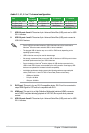
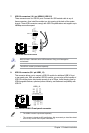
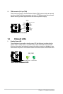
10. Intel
®
H81 Serial ATA 3.0 Gb/s connectors (7-pin SATA3G 1~2 [brown])
These connectors are for the Serial ATA 3.0 Gb/s signal cables for Serial ATA hard disk
drives and optical disc drives.
H81I-PLUS
H81I-PLUS SATA 3.0Gb/s connectors
SATA3G_1
GND
RSATA_TXP1
RSATA_TXN1
GND
RSATA_RXN1
RSATA_RXP1
GND
SATA3G_2
GND
RSATA_TXP2
RSATA_TXN2
GND
RSATA_RXN2
RSATA_RXP2
GND