


2-12 Chapter 2: Hardware information
A
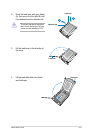
REMOVE
B
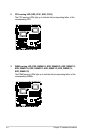
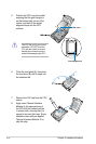
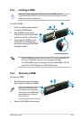
6. Close the load plate (A), then push
the load lever (B) until it snaps into
the retention tab.
7. Remove the PnP cap from the CPU
socket.
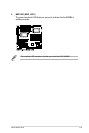
8. Apply some Thermal Interface
Material to the exposed area of
the CPU that the heatsink will be
in contact with, ensuring that it is
spread in an even thin layer. Some
heatsinks come with pre-applied
Thermal Interface Material. If so,
skip this step.
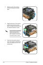
The CPU ts in only one correct
orientation. DO NOT force the
CPU into the socket to prevent
bending the connectors on the
socket and damaging the CPU!
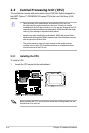
5. Position the CPU over the socket,
ensuring that the gold triangle is
on the bottom-right corner of the
socket, and then t the socket
alignment keys into the CPU
notches.
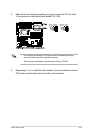
Gold triangle mark
CPU notch