


ASUS M2A-VM HDMI 1-31
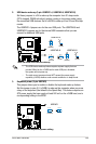
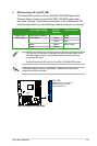
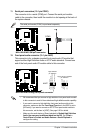
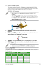
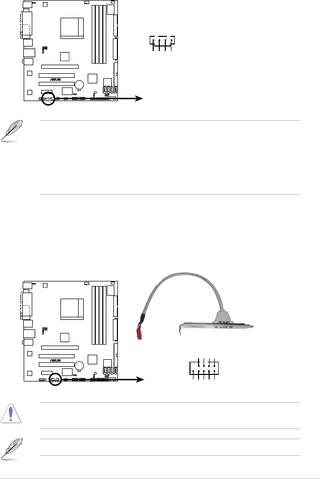
10. IEEE 1394a connector (10-1 pinIE1394_2 [red])
This connector is for an additional IEEE 1394a port. Connect the IEEE 1394a
module cable (orange) to this connector, then install the module to a slot
opening at the back of the system chassis.
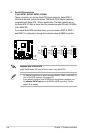
Never connect a USB port module cable to the IEEE 1394a connector. Doing so
will damage the motherboard!
M2A-VM HDMI
®
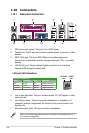
M2A-VM HDMI IEEE 1394a connector
IE1394_2
PIN1
GND
+12V
TPB1-
GND
TPA1-
+12V
TPB1+
GND
TPA1+
The IEEE1394a module is purchased separately.
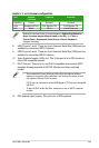
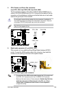
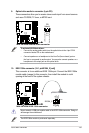
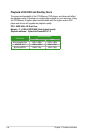
9. Optical drive audio in connector (4-pin CD)
These connectors allow you to receive stereo audio input from sound sources
such as a CD-ROM, TV tuner, or MPEG card.
M2A-VM HDMI
®
M2A-VM HDMI Internal audio connector
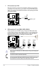
CD
(black)
Right Audio Channel
Left Audio Channel
Ground
Ground
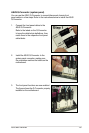
To activate ASUS Music Alarm:
• Connect the analog audio cable from the optical drive to the 4-pin CD-IN
connector labeled CD on the motherboard.
• Connect speakers or a headphone to the Line-Out (lime-colored) port on
the front or rear panel for audio output. You may also connect speakers or a
headphone to the output jack on the optical drive.