


1-32 Chapter 1: Product introduction
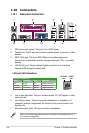
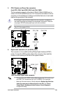
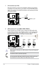
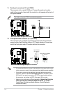
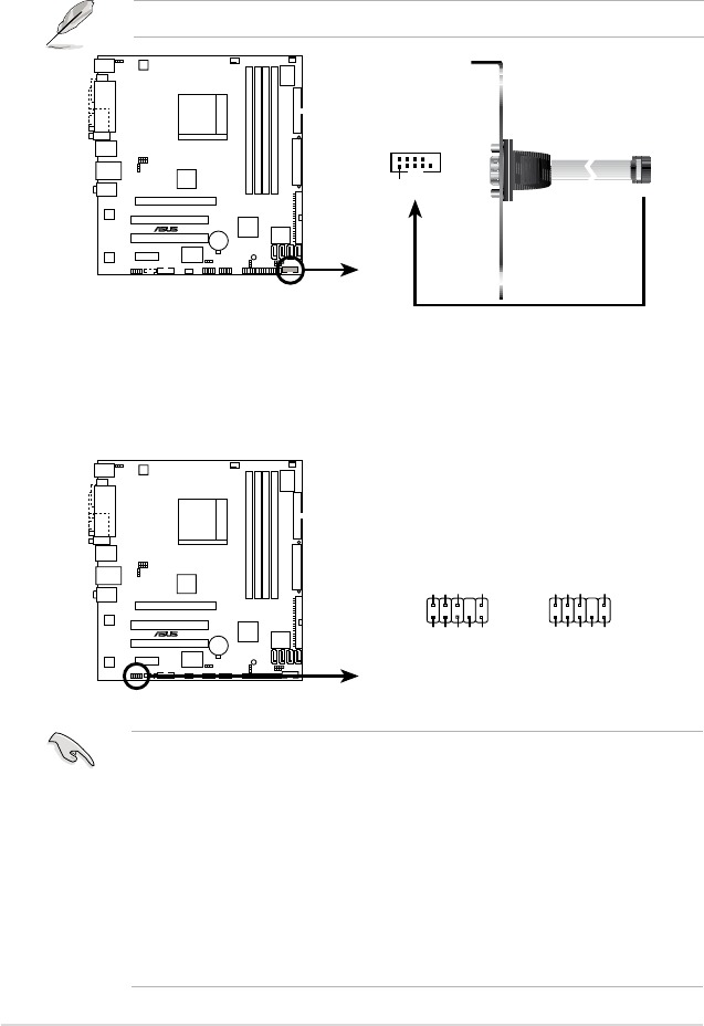
11. Serial port connectors (10-1 pin COM1)
The connector is for a serial (COM) port. Connect the serial port module
cable to the connector, then install the module to a slot opening at the back of
the system chassis.
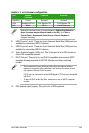
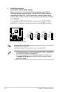
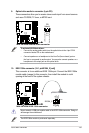
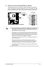
12. Front panel audio connector (10-1 pin AAFP)
This connector is for a chassis-mounted front panel audio I/O module that
supports either High Denition Audio or AC’97 audio standard. Connect one
end of the front panel audio I/O module cable to this connector.
• We recommend that you connect a high-denition front panel audio module
to this connector to avail of the motherboard high-denition audio capability.
• If you want to connect a high-denition front panel audio module to this
connector, make sure that the Front Panel Type item in the BIOS is set to
[HD Audio]; if you want to connect an AC’97 front panel audio module to
this connector, set the item to [AC97]. See page 2-25 for details.
• Make sure the audio device of Sound playback is
Realtek High Denition
Audio (the name may be different based on the OS). Go to Start >
Control Panel > Sounds and Audio Devices > Sound Playback to
congure the setting.
The serial port bracket (COM1) is purchased separately.
M2A-VM HDMI
®
M2A-VM HDMI COM port connector
PIN 1
COM1
M2A-VM HDMI
®
M2A-VM HDMI Analog front panel connector
AAFP
High-definition
pin definition
Legacy AC’97-compliant
pin definition
NC
MIC2
Line out_R
Line out_L
NC
NC
MICPWR
NC
AGND
PORT1 R
SENSE2_RETUR
PORT1 L
PORT2 R
PORT2 L
SENSE1_RETUR
SENSE_SEND
PRESENCE#
GND