


1-32 Chapter 1: Product introduction
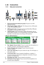
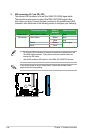
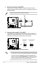
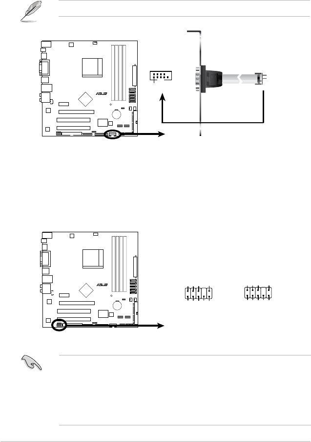
9. Serial port connectors (10-1 pin COM1)
The connector is for a serial (COM) port. Connect the serial port module
cable to the connector, then install the module to a slot opening at the back of
the system chassis.
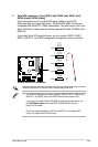
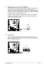
10. Front panel audio connector (10-1 pin AAFP)
This connector is for a chassis-mounted front panel audio I/O module that
supports either High Denition Audio or AC`97 audio standard. Connect one
end of the front panel audio I/O module cable to this connector.
• We recommend that you connect a high-denition front panel audio module
to this connector to avail of the motherboard high-denition audio capability.
• If you want to connect a high-denition front panel audio module to this
connector, ensure that the Front Panel Type item in the BIOS is set to [HD
Audio]; if you want to connect an AC`97 front panel audio module to this
connector, set the item to [AC97]. See page 2-29 for details.
The serial port bracket (COM1) is purchased separately.
R
M3N78-VM
M3N78-VM
COM Port Connector
PIN1
COM1
R
M3N78-VM
M3N78-VM Azalia Analog Front Panel Connector
HP_HD
MIC2_L
HP_R
HP_L
MIC2_JD
Jack_Sense
MIC2_R
PRESENSE#
AGND
AAFP
LegacyAC’97-compliant
pin definition
NC
MIC2_L
Line out_R
Line out_L
NC
NC
MIC2_R
NC
AGND
Azalia-compliant
pin definition