


ASUS A7N8X-VM Motherboard
1-17
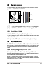
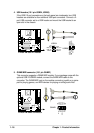
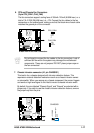
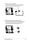
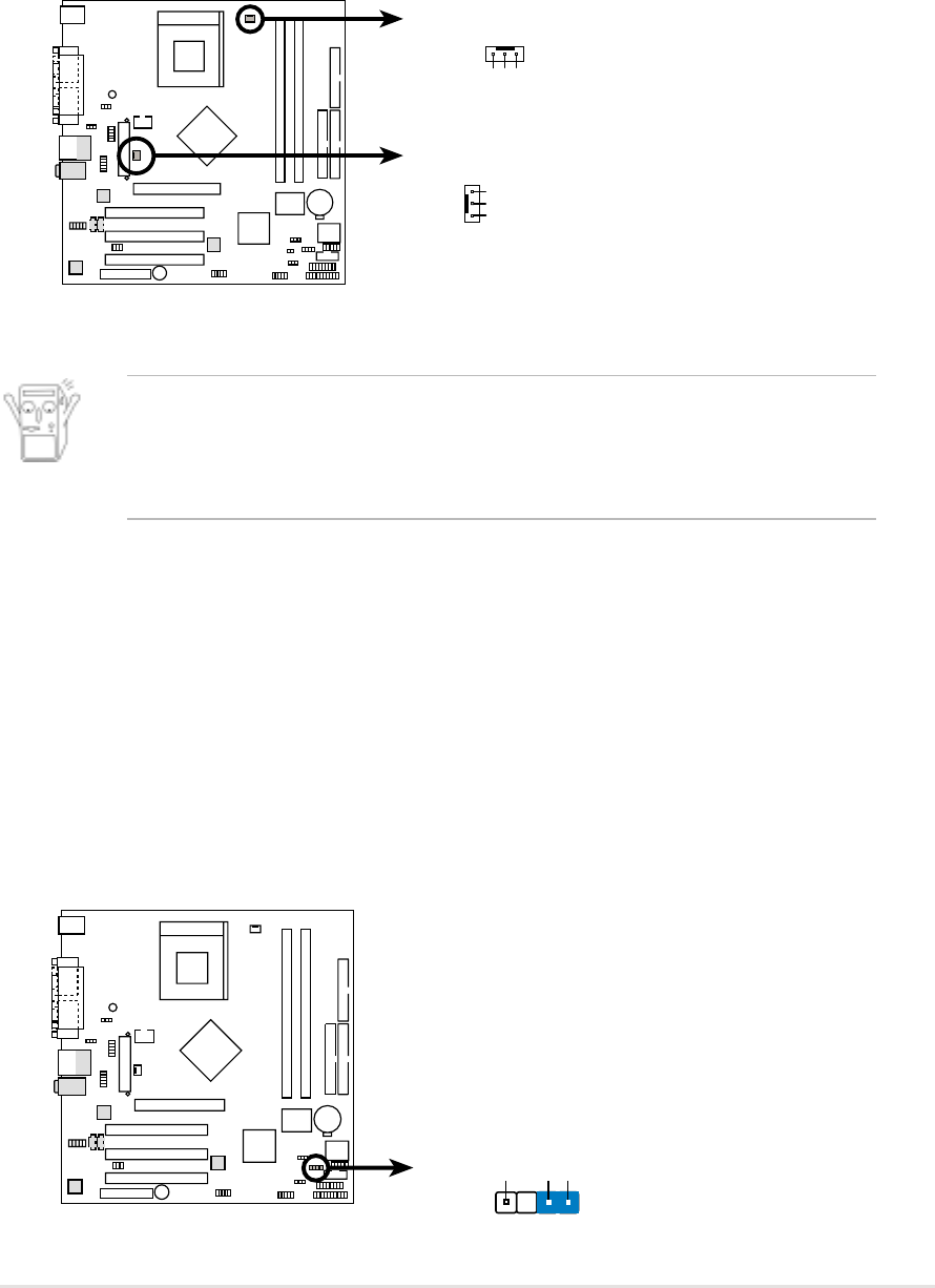
6. CPU and Chassis Fan Connectors
(3-pin CPU_FAN1, CHA_FAN)
The fan connectors support cooling fans of 350mA~740mA (8.88W max.) or a
total of 1A~2.22A (26.64W max.) at +12V. Connect the fan cables to the fan
connectors on the motherboard, making sure that the black wire of each cable
matches the ground pin of the connector.
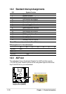
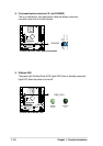
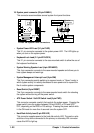
7. Chassis intrusion connector (4-1 pin CHASSIS1)
This lead is for a chassis designed with intrusion detection feature. This
requires an external detection mechanism such as a chassis intrusion sensor
or microswitch. When you remove any chassis component, the sensor triggers
and sends a high-level signal to this lead to record a chassis intrusion event.
By default, the pins labeled “Chassis Signal” and “Ground” are shorted with a
jumper cap. If you wish to use the chassis intrusion detection feature, remove
the jumper cap from the pins.
A7N8X-VM 12-Volt Fan Connectors
CHA_FAN
CPU_FAN1
GND
Rotation
+12V
GND
Rotation
+12V
A7N8X-VM
A7N8X-VM Chassis Alarm Lead
CHASSIS1
+5VSB_MB
Chassis Signal
GND
(Default)
A7N8X-VM
Do not forget to connect the fan cables to the fan connectors. Lack of
sufficient air flow within the system may damage the motherboard
components. These are not jumpers! DO NOT place jumper caps on
the fan connectors!