


1-22
Chapter 1: Product Information
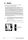
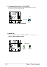
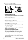
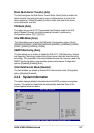
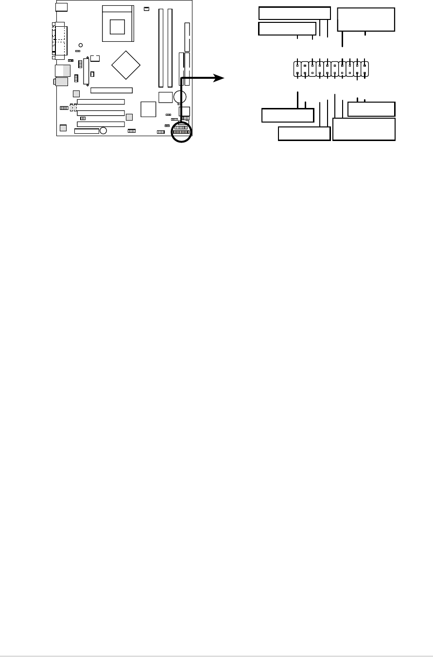
16. System panel connector (20-pin PANEL1)
This connector accommodates several system front panel functions.
A7N8X-VM System Panel Connectors
* Requires an ATX power supply.
PLED-
Ground
PWR
Keylock
+5V
Speaker
Speaker
Connector
Power LED
Ground
Reset SW
SMI Lead
ExtSMI#
Ground
Reset
Ground
Ground
Ground
Keyboard Lock
ATX Power
Switch*
PLED+
IDELED
+5V
IDE LED
A7N8X-VM
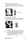
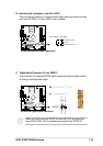
• System Power LED Lead (3-1 pin PLED)
This 3-1 pin connector connects to the system power LED. The LED lights up
when you turn on the system power.
• Keyboard Lock Lead (2-1 pin KEYLOCK)
This 2-1 pin connector connects to the case-mounted switch to allow the use of
the keyboard lock feature.
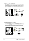
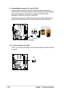
• System Warning Speaker Lead (4-pin SPEAKER)
This 4-pin connector connects to the case-mounted speaker and allows you to
hear system beeps and warnings.
• System Management Interrupt Lead (2-pin SMI)
This 2-pin connector permits switching to suspend mode, or “Green” mode, in
which system activity is instantly decreased to save power and to expand the
life of certain system components.
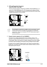
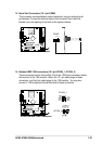
• Reset Switch (2-pin RESET)
This 2-pin connector connects to the case-mounted reset switch for rebooting
the system without turning off the power switch.
• ATX Power Switch / Soft-Off Switch Lead (2-pin PWR)
This connector connects a switch that controls the system power. Pressing the
power switch turns the system between ON and SLEEP, or ON and SOFT
OFF, depending on the BIOS or OS settings. Pressing the power switch while
in the ON mode for more than 4 seconds turns the system OFF.
• Hard Disk Activity Lead (2-pin IDE LED)
This connector supplies power to the hard disk activity LED. The read or write
activities of any device connected to the primary or secondary IDE connector
cause this LED to light up.