


2-24 Chapter 2: Hardware information
2.7.2 Internal connectors
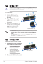
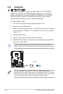
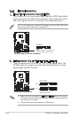
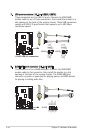
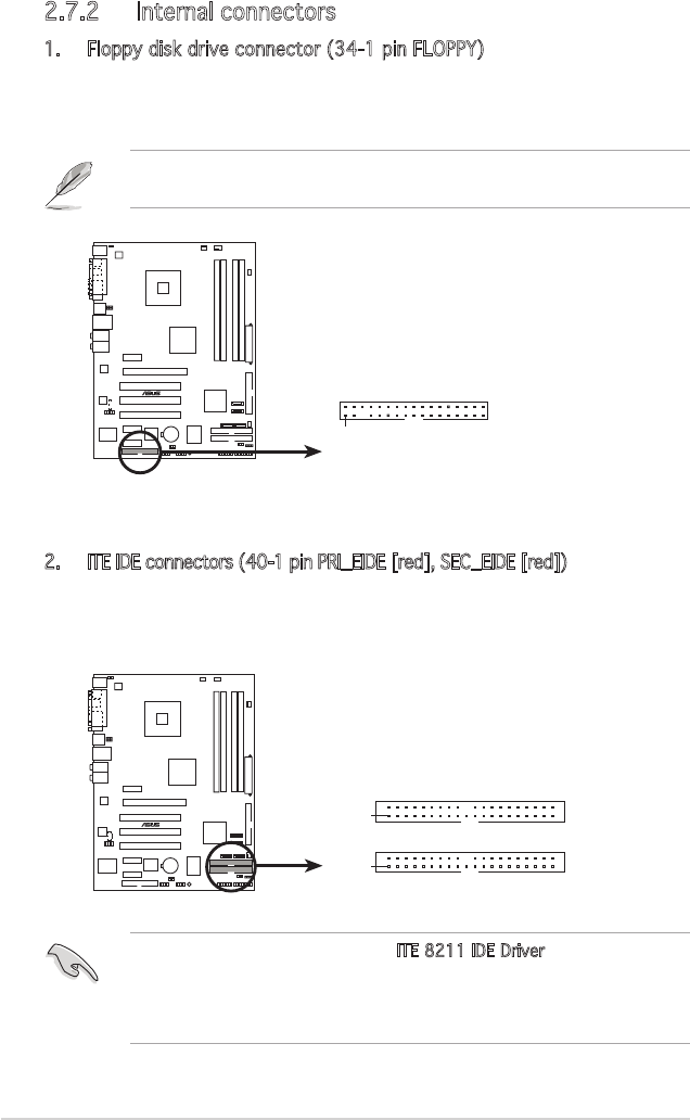
1. Floppy disk drive connector (34-1 pin FLOPPY)
This connector is for the provided oppy disk drive (FDD) signal cable.
Insert one end of the cable to this connector, then connect the other
end to the signal connector at the back of the oppy disk drive.
Pin 5 on the connector is removed to prevent incorrect cable connection
when using a FDD cable with a covered Pin 5.
P5LD2
®
NOTE: Orient the red markings on
the floppy ribbon cable to PIN 1.
P5LD2 Floppy disk drive connector
PIN 1
FLOPPY
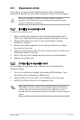
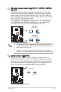
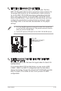
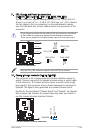
2. ITE IDE connectors (40-1 pin PRI_EIDE [red], SEC_EIDE [red])
These connectors are for Ultra ATA 133/100/66 signal cables. The
ITE IDE connectors support up to four IDE hard disk drives for easier
data storage and data transfer.
P5LD2
®
P5LD2 RAID connectors
NOTE: Orient the red markings
(usually zigzag) on the IDE
ribbon cable to PIN 1.
PRI_EIDE
SEC_EIDE
PIN 1
PIN 1
• Make sure that you install the ITE 8211 IDE Driver from the support
CD before using the IDE device attached to any of these connectors.
See Chapter 5 for details.
• These connectors do not support ATAPI devices.