


ASUS P5LD2 2-25
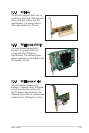
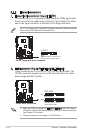
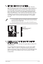
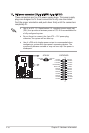
4. Serial ATA connectors (7-pin SATA1 [red], SATA2 [red], SATA3
[black], SATA4 [black])
These connectors are for the Serial ATA signal cables for Serial ATA
hard disk drives.
If you installed Serial ATA hard disk drives, you can create a RAID
0, RAID 1, RAID 5, or RAID 10 conguration with the Intel
®
Matrix
Storage Technology through the onboard Intel
®
ICH7R RAID controller.
Refer to Chapter 5 for details on how to set up Serial ATA RAID
congurations.
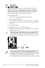
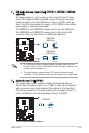
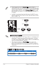
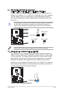
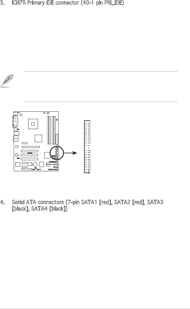
3. ICH7R Primary IDE connector (40-1 pin PRI_IDE)
This connector is for an Ultra DMA 100/66 signal cable. The Ultra
DMA 100/66 signal cable has three connectors: a blue connector for
the primary IDE connector on the motherboard, a black connector
for an Ultra DMA 100/66 IDE slave device (optical drive/hard disk
drive), and a gray connector for an Ultra DMA 100/66 IDE master
device (hard disk drive). If you install two hard disk drives, you must
congure the second drive as a slave device by setting its jumper
accordingly. Refer to the hard disk documentation for the jumper
settings.
• Pin 20 on the IDE connector is removed to match the covered hole
on the Ultra DMA cable connector. This prevents incorrect insertion
when you connect the IDE cable.
• Use the 80-conductor IDE cable for Ultra DMA 100/66 IDE devices.
P5LD2
®
P5LD2 IDE connector
NOTE: Orient the red markings
(usually zigzag) on the IDE
ribbon cable to PIN 1.
PRI_IDE
PIN 1