


2-62-6
2-62-6
2-6
Chapter 2: Hardware informationChapter 2: Hardware information
Chapter 2: Hardware informationChapter 2: Hardware information
Chapter 2: Hardware information
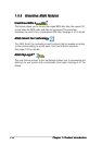
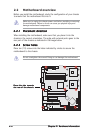
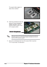
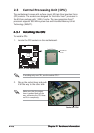
10. Install the motherboard with the
external I/O ports toward the
chassis rear panel. The CPU
sockets should be right on top
of the support plates.
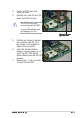
11. Secure the motherboard with nine (9) screws. Refer to section
“2.2.2 Screw holes” for illustration.
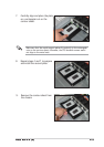
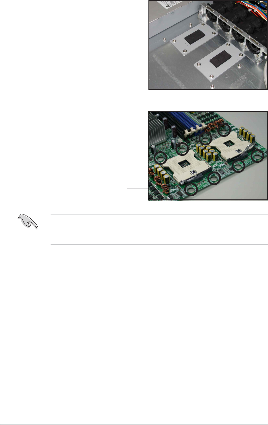
The support plates appear as
shown when installed.
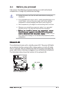
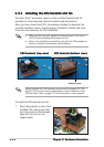
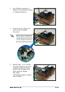
Make sure that the CPU heatsink holes on the motherboard perfectly
match the metal nuts on the support plates; otherwise, you can not
install the CPU heatsinks properly.
Heatsink hole matched toHeatsink hole matched to
Heatsink hole matched toHeatsink hole matched to
Heatsink hole matched to
a nut on the support platea nut on the support plate
a nut on the support platea nut on the support plate
a nut on the support plate