


2-342-34
2-342-34
2-34
Chapter 2: Hardware informationChapter 2: Hardware information
Chapter 2: Hardware informationChapter 2: Hardware information
Chapter 2: Hardware information
NCLV-D
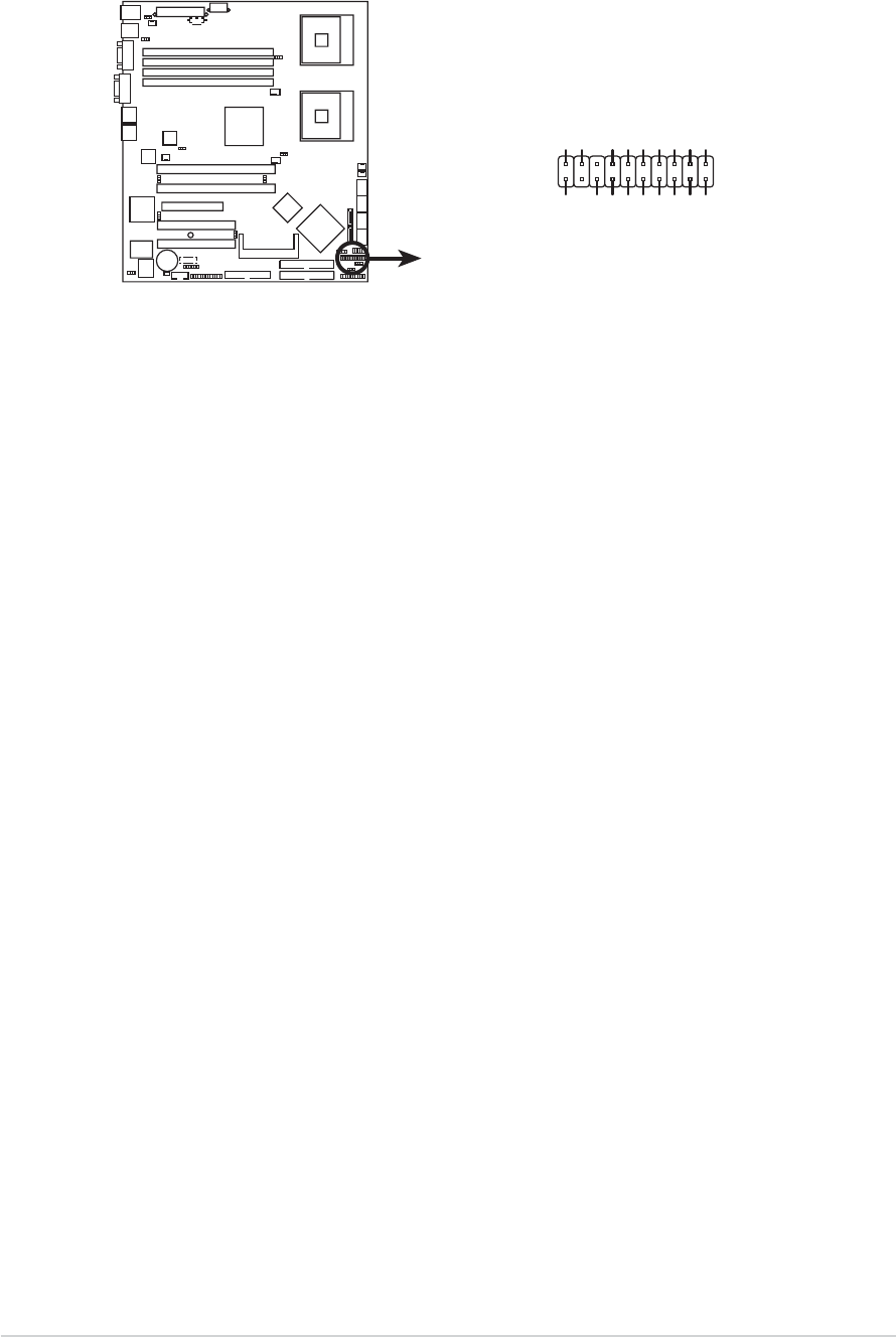
NCLV-D Auxiliary panel connector
AUX_PANEL1
I2C_4_DATA#LOCATORLED1+
+3VLOCATORLED1-
LAN1_LINKACTLED+LOCATORBTN#
LAN1_LINKACTLED-GND
+5VSB
I2C_4_CLK#
GNDGND
LAN2_LINKACTLED-LOCATORLED2-
LAN2_LINKACTLED+LOCATORLED2+
CASEOPEN
PIN1
NC
14.14.
14.14.
14.
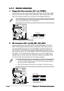
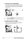
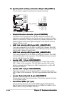
System panel auxiliary connector (20-pin AUX_PANEL1)System panel auxiliary connector (20-pin AUX_PANEL1)
System panel auxiliary connector (20-pin AUX_PANEL1)System panel auxiliary connector (20-pin AUX_PANEL1)
System panel auxiliary connector (20-pin AUX_PANEL1)
This connector supports several server system functions.
•
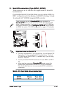
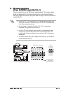
Chassis Intrusion connector (3-pin CASEOPEN)Chassis Intrusion connector (3-pin CASEOPEN)
Chassis Intrusion connector (3-pin CASEOPEN)Chassis Intrusion connector (3-pin CASEOPEN)
Chassis Intrusion connector (3-pin CASEOPEN)
This lead is for a chassis with an intrusion detection feature. This
requires an external detection mechanism such as a chassis intrusion
sensor or microswitch. When you remove any chassis component, the
sensor triggers and sends a high-level signal to this lead to record a
chassis intrusion event.
•
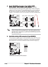
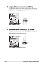
LAN1 link activity LED (2-pin LAN1_LINKACTLED)LAN1 link activity LED (2-pin LAN1_LINKACTLED)
LAN1 link activity LED (2-pin LAN1_LINKACTLED)LAN1 link activity LED (2-pin LAN1_LINKACTLED)
LAN1 link activity LED (2-pin LAN1_LINKACTLED)
This 2-pin connector is for the LAN1 Activity LED. Connect the LAN1
Activity LED cable to this connector. This LED blinks during a network
activity and is always lit when linked.
•
LAN2 link activity LED (2-pin LAN2_LINKACTLED)LAN2 link activity LED (2-pin LAN2_LINKACTLED)
LAN2 link activity LED (2-pin LAN2_LINKACTLED)LAN2 link activity LED (2-pin LAN2_LINKACTLED)
LAN2 link activity LED (2-pin LAN2_LINKACTLED)
This 2-pin connector is for the LAN2 Activity LED. Connect the LAN2
Activity LED cable to this connector. This LED blinks during a network
activity and lights up when linked.
•
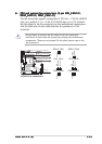
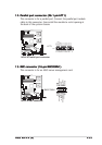
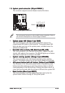
Locator LED 1 (2-pin LOCATORLED1)Locator LED 1 (2-pin LOCATORLED1)
Locator LED 1 (2-pin LOCATORLED1)Locator LED 1 (2-pin LOCATORLED1)
Locator LED 1 (2-pin LOCATORLED1)
This 2-pin connector is for the Locator LED 1. Connect the Locator
LED 1 cable to this connector. This LED lights up when the Locator
button is pressed and if there is no LAN1 connection (e.g. the LAN1
controller is broken).
•
Locator LED 2 (2-pin LOCATORLED2)Locator LED 2 (2-pin LOCATORLED2)
Locator LED 2 (2-pin LOCATORLED2)Locator LED 2 (2-pin LOCATORLED2)
Locator LED 2 (2-pin LOCATORLED2)
This 2-pin connector is for the Locator LED 2. Connect the Locator
LED 2 cable to this connector. This LED is synchronized with the LAN2
LED.
•
Locator Button/Switch (2-pin LOCATORBTN)Locator Button/Switch (2-pin LOCATORBTN)
Locator Button/Switch (2-pin LOCATORBTN)Locator Button/Switch (2-pin LOCATORBTN)
Locator Button/Switch (2-pin LOCATORBTN)
This connector is for the locator button. This button queries the state
of the system locator.
•
Front Panel SMBus (6-1 pin)Front Panel SMBus (6-1 pin)
Front Panel SMBus (6-1 pin)Front Panel SMBus (6-1 pin)
Front Panel SMBus (6-1 pin)
This connector allows you to connect SMBus (System Management
Bus) devices. Devices communicate with an SMBus host and/or other
SMBus devices using the SMBus interface.