


ASUS P2B-F User’s Manual 27
III. HARDWARE SETUP
DMA Channels
III. H/W SETUP
Connectors
III. H/W SETUP
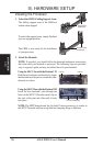
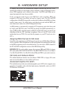
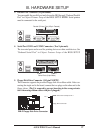
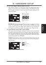
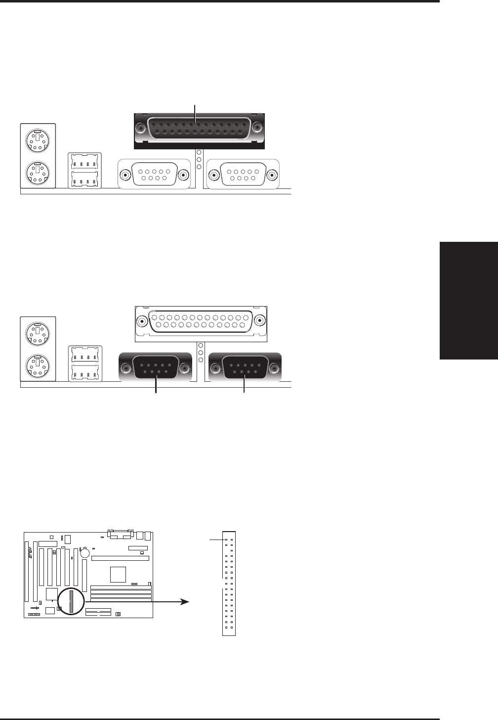
3. Parallel Port Connector (25-pin female)
You can enable the parallel port and choose the IRQ through “Onboard Parallel
Port” in Chipset Features Setup of the BIOS SETUP. NOTE: Serial printers
must be connected to the serial port.
Parallel (Printer) Port (25-pin Female)
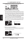
4. Serial Port COM1 and COM2 Connectors (Two 9-pin male)
The two serial ports can be used for pointing devices or other serial devices. See
“Onboard Serial Port” in Chipset Features Setup of the BIOS SETUP.
COM 1 COM 2
Serial Ports (9-pin Male)
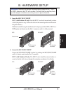
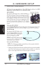
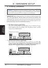
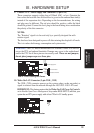
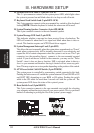
5. Floppy Disk Drive Connector (34-1pin FLOPPY)
This connector supports the provided floppy disk drive ribbon cable. After con-
necting the single end to the board, connect the two plugs on the other end to the
floppy drives. (Pin 5 is removed to prevent inserting in the wrong orienta-
tion when using ribbon cables with pin 5 plugged).
R
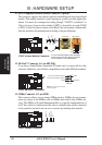
P2B-F Floppy Disk Drive Connector
NOTE: Orient the red stripe to Pin 1
Floppy Drive Connector
Pin 1