


30 ASUS P2B-F User’s Manual
III. HARDWARE SETUP
Connectors
III. H/W SETUP
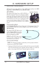
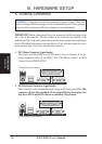
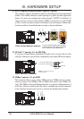
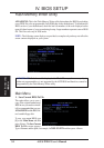
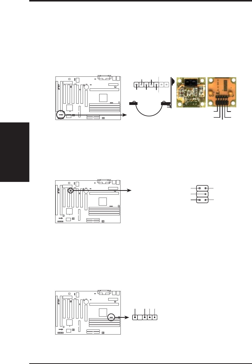
11. IrDA-Compliant Infrared Module Connector (5-pin IR)
This connector supports the optional wireless transmitting and receiving infrared
module. This module mounts to a small opening on system cases that support this
feature. You must also configure the setting through “UART2 Use Infrared” in
Chipset Features Setup to select whether UART2 is directed for use with COM2
or IrDA. Use the five pins as shown on the Back View and connect a ribbon cable
from the module to the motherboard according to the pin definitions.
Front View
+5V
IRTX
IRRX
(NC)
GND
Back View
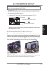
P2B-F Infrared Module Connector
For the infrared feature to be available,
you must connect the optional Infrared
(IrDA) module to the motherboard
R
+5V
GND
IRTX
(NC)
IRRX
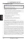
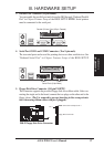
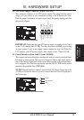
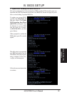
12. SB-Link™ Connector (6-1 pin SBLINK)
If you have a Sound Blaster compatible PCI audio card, you must link it to this
connector. Otherwise, you will have compatibility issues under DOS environment.
SBLINK
Serial IRQ
PC/PCI Request Sideband Signal
PC/PCI Grant Sideband Signal
DGND
21
56
NOTE: Pin 3 is removed to ensure
correct orientation.
DGND
P2B-F SB-Link™ Connector
R
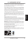
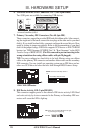
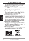
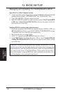
13. SMBus Connector (5-1 pin SMB)
This connector allows you to connect SMBus devices. SMBus devices commu-
nicate by means of the SMBus with an SMBus host and/or other SMBus de-
vices. The SMBus or System Management Bus is a specific implementation of
an I
2
C bus, which is a multi-master bus, that is, multiple chips can be connected
to the same bus and each one can act as a master by initiating data transfer.
P2B-F SMBus Connector
R
SMBCLK
Ground
SMBDATA
+5V
1