


ASUS P2B-F User’s Manual 31
III. HARDWARE SETUP
Connectors
III. H/W SETUP
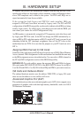
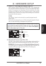
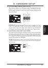
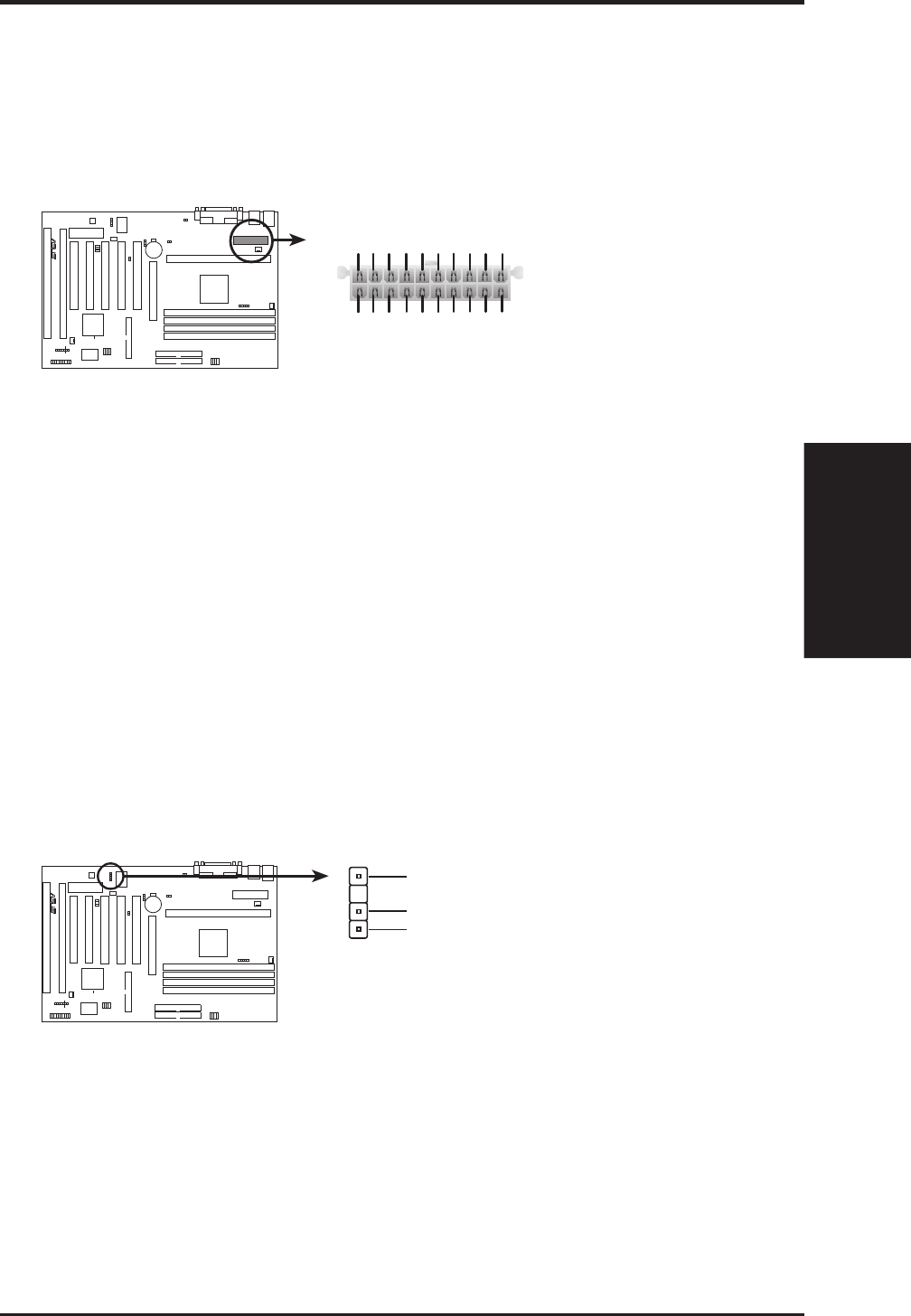
14. ATX Power Supply Connector (20-pin ATXPWR)
This connector connects to an ATX power supply. The plug from the power
supply will only insert in one orientation because of the different hole sizes.
Find the proper orientation and push down firmly but gently making sure that
the pins are aligned.
P2B-F ATX Power Connector
+3.3Volts
-12.0Volts
Ground
Power Supply On
Ground
Ground
Ground
-5.0 Volts
+5.0 Volts
+5.0 Volts
Power Good
+12.0Volts
+3.3 Volts
+3.3 Volts
Ground
+5.0 Volts
Ground
+5.0 Volts
Ground
+5V Standby
R
IMPORTANT: Make sure that your ATX power supply can supply at least 10mA
on the 5-volt standby lead (5VSB). You may experience difficulty in powering
on your system if your power supply cannot support the load. For Wake-On-
LAN support, your ATX power supply must supply at least 720mA +5VSB.
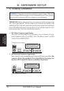
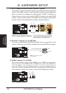
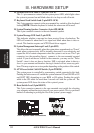
15. Chassis Intrusion Alarm Lead (4-1 pin CHASSIS)
This requires an external detection mechanism such as a chassis intrusion moni-
tor/sensor or microswitch. The sensor is triggered when a high level signal is
sent to the Chassis Signal lead, which occurs when a panel switch or light detec-
tor is triggered. This function requires the optional ASUS CIDB chassis sensor
module to be installed (See APPENDIX).
NOTE: When the chassis is opened, connect/short the Chassis Signal pin to the
+5VSB pin. When the chassis is closed, connect/short the Chassis Signal pin to
the Ground pin.
P2B-F Chassis Intrusion Alarm Lead
+5VSB
Chassis Signal
GND
R