


ASUS P3V133 User’s Manual 35
3. HARDWARE SETUP
Connectors
3. H/W SETUP
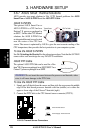
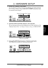
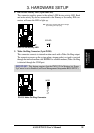
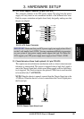
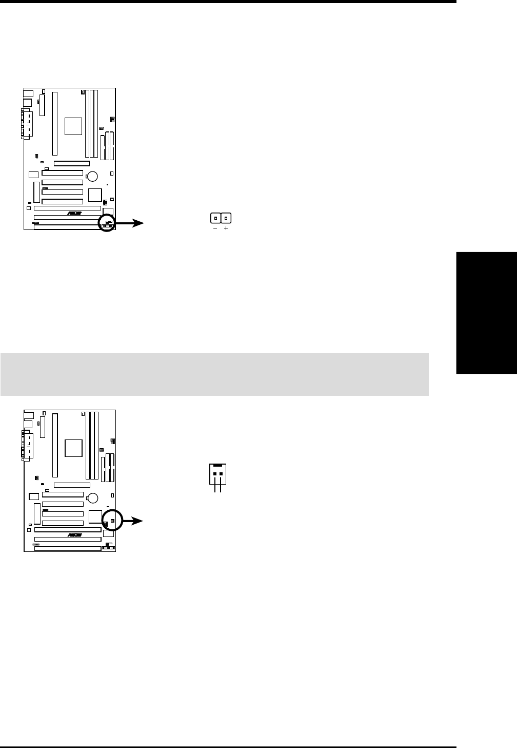
8. IDE Device Activity LED (2-pin IDELED)
This connector supplies power to the cabinet’s IDE device activity LED. Read
and write activity by devices connected to the Primary or Secondary IDE con-
nectors will cause the LED to light up.
P3V133 IDE Activity LED
TIP: If the case-mounted LED does not light,
try reversing the 2-pin plug.
IDELED
R
P3V133
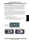
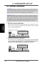
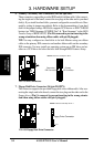
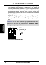
9. Wake-On-Ring Connector (2-pin WOR)
This connector connects to internal modem cards with a Wake-On-Ring output.
The connector powers up the system when a ringup packet or signal is received
through the internal modem card. NOTE: For external modems, Wake-On-Ring
is detected through the COM port.
IMPORTANT: This feature requires that the PWR UP On Modem Act Power
Up Control is set to Enabled (see Power Management Setup under BIOS SETUP).
P3V133 Wake-On-Ring Connector
WOR
Pin 2 PIXRI#
Pin1 Ground
R
P3V133