


ASUS P3V133 User’s Manual88
7. APPENDIX
7. APPENDIX
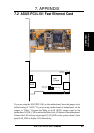
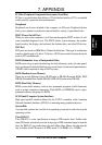
S370-133 CPU Card
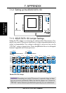
7.1.2 Setting up the ASUS S370-133
Socket 370
JP1
JP2
JP3
JP4
JP5
CPU Voltage
Screw Hole
Screw Hole
Brown Lever
JP6
R
S370-133
(Default)
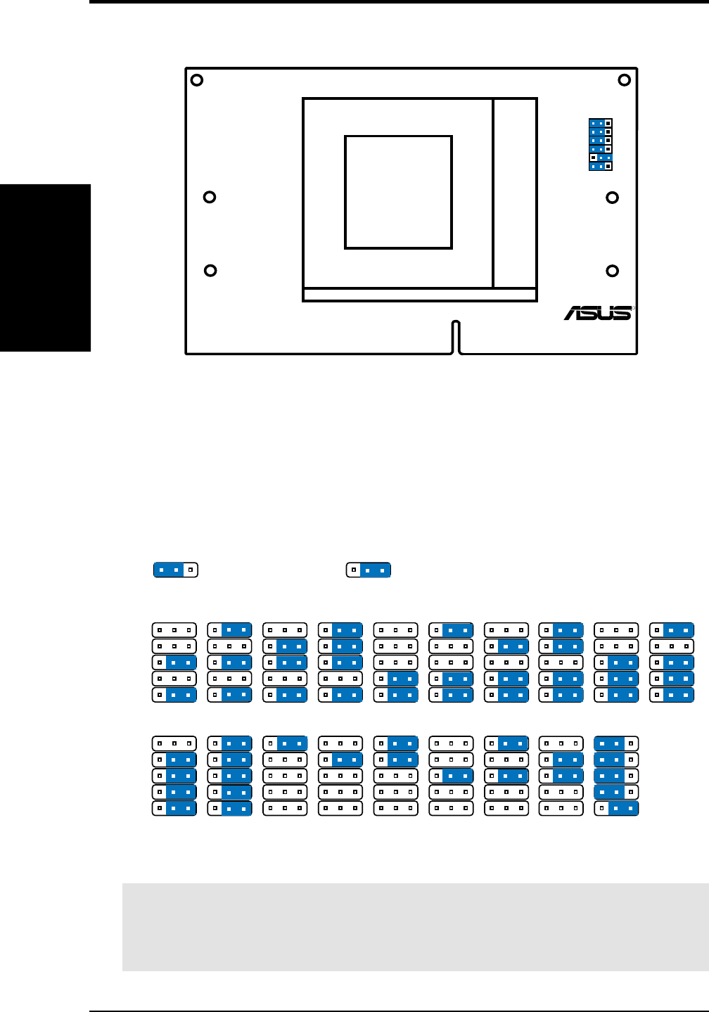
Socket 370 CPU Voltage
1.50Volts
123
1.55Volts
123
1.60Volts
123
1.65Volts
123
1.75Volts
123
1.70Volts
123
1.80Volts
123
2.00Volts
123
2.05Volts
123
2.10Volts
123
2.20Volts
123
2.40Volts
123
2.30Volts
123
2.50Volts
123
JP1
JP2
JP3
JP4
JP5
JP1
JP2
JP3
JP4
JP5
1.90Volts
123
1.85Volts
123
1.95Volts
123
CPU Def.
(Default)
123
2.60Volts
123
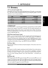
JP6
123 123
For Coppermine Processors
(Default)
JP6
For Celeron Processors
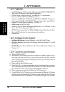
7.1.3 ASUS S370-133 Jumper Settings
Setting the CPU voltage is not necessary for current socket 370 processors. If re-
quired, your socket 370 processor should have its voltage requirement printed on its
surface or documentation. If no voltage is indicated or you are not sure, use the
“CPU Def.” setting as shown below. Notice that JP6 should be set to distinguish
between Coppermine and Celeron processors.
WARNING! Exceeding your socket 370 processor’s required voltage can dam-
age your processor permanently! Make sure that the jumpers are as shown for
“CPU Def.” unless otherwise specified before powering on your motherboard.