


18 ASUS P3V4X User’s Manual
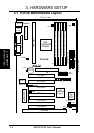
3. HARDWARE SETUP
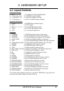
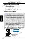
Motherboard Settings
3. H/W SETUP
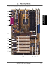
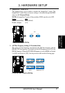
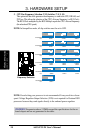
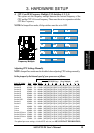
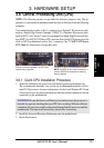
3. CPU Bus Frequency Selection (U12–Switches 7, 8, 9, 10)
This option tells the clock generator what frequency to send to the CPU, DRAM, and
PCI bus. This allows the selection of the CPU’s External frequency (or BUS Clock).
The BUS Clock multiplied by the BUS Multiple equals the CPU’s Internal frequency
(the advertised CPU speed).
NOTE: In JumperFree mode, all dip switches must be set to OFF.
R
P3V4X
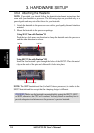
P3V4X CPU External
Frequency Selection
112MHz
37MHz
66MHz
33MHz
103MHz
34MHz
68MHz
34MHz
100MHz
33MHz
120MHz
40MHz
75MHz
37MHz
80MHz
40MHz
CPU/DRAM
PCI
83MHz
42MHz
CPU/DRAM
PCI
CPU/DRAM
PCI
ON
12345678910
ON
12345678910
ON
12345678910
ON
12345678910
ON
12345678910
ON
12345678910
ON
12345678910
ON
12345678910
ON
12345678910
115MHz
38MHz
110MHz
36MHz
CPU/DRAM
PCI
ON
12345678910
ON
12345678910
105MHz
35MHz
ON
12345678910
140MHz
35MHz
150MHz
37MHz
CPU/DRAM
PCI
ON
12345678910
ON
12345678910
124MHz
31MHz
133MHz
33MHz
ON
12345678910
ON
12345678910
CPU/DRAM
PCI
NOTE: Overclocking your processor is not recommended. It may result in a slower
speed. Voltage Regulator Output Selection (VID) is not required for Pentium III/II
processors because they send signals directly to the onboard power regulator.
WARNING! Frequencies above 133MHz exceed the specifications for the on-
board chipset and are not guaranteed to be stable.