


36 ASUS P3V4X User’s Manual
3. HARDWARE SETUP
Connectors
3. H/W SETUP
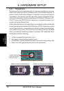
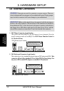
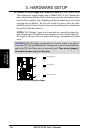
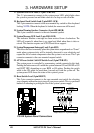
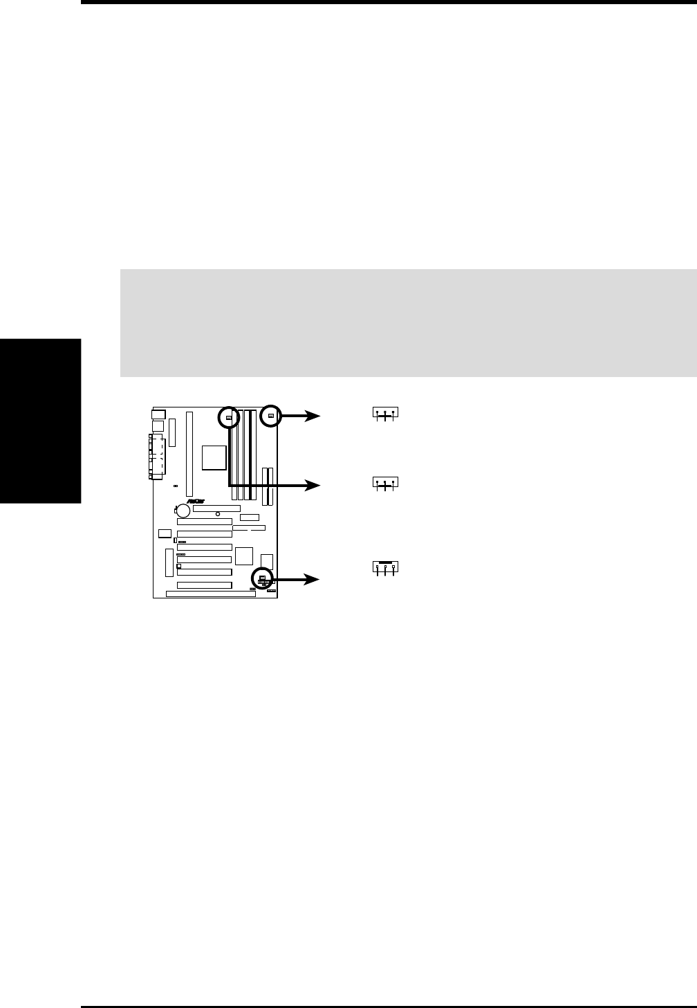
10. Chassis/CPU/Power Supply Fan Connectors (3-pin CHA_,CPU_,PWR_FAN)
These connectors support cooling fans of 500mA (6W) or less. Orientate the
fans so that the heat sink fins allow airflow to go across the onboard heat sink(s)
instead of the expansion slots. Depending on the fan manufacturer, the wiring
and plug may be different. The red wire should be positive, while the black
should be ground. Connect the fan’s plug to the board taking into consideration
the polarity of the this connector.
NOTES: The “Rotation” signal is to be used only by a specially designed fan
with rotation signal. The fans have been designed to power off after entering
the sleep/soft-off mode. This is to reduce both energy consumption and system
noise.
WARNING! The CPU and/or motherboard will overheat if there is no airflow
across the CPU and onboard heatsinks. Damage may occur to the motherboard
and/or the CPU fan if these pins are incorrectly used. These are not jumpers,
do not place jumper caps over these pins.
R
P3V4X
P3V4X 12Volt Cooling Fan Power
Power Supply Fan
Chassis Fan Power
CPU Fan Power
GND
+12V
Rotation
GND
+12V
Rotation
GND
+12V
Rotation