


2-2
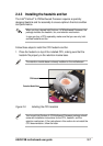
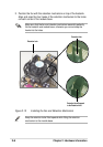
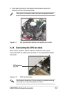
Chapter 2: Hardware information
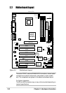
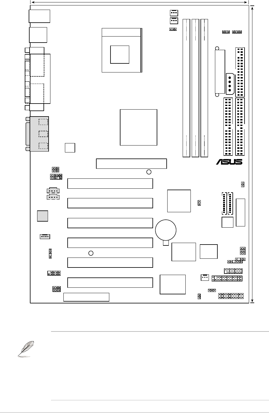
2.2 Motherboard layout
The audio CODEC, external GAME/AUDIO connectors, internal audio
connectors are optional components, and present in audio models
only. The components are grayed in the above motherboard layout.
For System Integrators:
The SD and MS connectors may or may not be mounted depending on
required specifications.
Figure 2-2 Motherboard Layout
DIMM Socket 1 (64/72-bit, 168-pin module)
0 1
DIMM Socket 2 (64/72-bit, 168-pin module)
2 3
DIMM Socket 3 (64/72-bit, 168-pin module)
4 5
2Mbit
Firmware
Hub
22cm (8.7in)
30.5cm (12.0in)
PWR_FAN
PCI1
PCI2
PCI4
PCI3
PANEL
FLOPPY
SECONDARY IDE
PRIMARY IDE
Intel I/O
Controller
Hub
(ICH2)
P4B
CHA_FAN
SWITCH
®
Accelerated Graphics Port
(AGP+1.5V)
ASUS
ASIC
with
Hardware
Monitor
CR2032 3V
Lithium Cell
CMOS Power
PCI5
ATX Power Connector
USB2
CPU_FAN
ATX12V
USBPWR1
JEN
COM1
PARALLEL PORT
COM2
PCI6
Socket 478
Intel 845
Memory
Controller
Hub (MCH)
LED1
CNR
PS/2KBMS
T: Mouse
B: Keyboard
USB1
USB2
SPDIFOUT
TRPWR
CD1
AUX
Super
I/O
MODEM
AFPANEL
SMARTCON
MS
SD
GAME_AUDIO
Mic
In
Line
Out
Line
In
SDRVOL
AUD_EN1
Audio
Codec
KBPWR
FUSB
AUX+12V
CHASSIS
SMB
SMART
CLRCMOS
SPEECH
AAPANEL
MICF
SPEAKER
HDLED
OVER_VOLT
WARNING