


ASUS P4B motherboard user guide
2-33
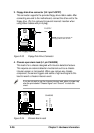
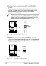
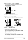
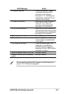
17. System panel connector (20-pin PANEL)
This connector accommodates several system front panel functions.
Figure 2-47 System Panel Connector
• System Power LED Lead (3-1 pin PWR.LED)
This 3-1 pin connector connects to the system power LED. The LED
lights up when you turn on the system power, and blinks when the
system is in sleep mode.
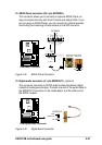
• Keyboard Lock Lead (2-pin KEYLOCK)
This 2-pin connector connects to a chassis-mounted switch to allow
the use of the keyboard lock feature.
P4B
®
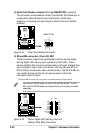
P4B System Panel Connectors
*
Requires an ATX power supply.
PLED
Ground
MLED
PWR
+5 V
Keylock
+5V
Speaker
Speaker
Connector
Power LED
Ground
+5 V
Reset SW
SMI Lead
Message LED
ExtSMI#
Ground
Reset
Ground
Ground
Ground
Keyboard Lock
ATX Power
Switch*
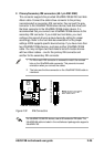
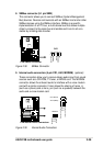
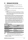
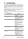
16. Power supply thermal connector (2-pin TRPWR)
If your power supply has a thermal monitoring feature, connect its
thermal sensor cable to this connector.
P4B
®
P4B Power Supply Thermal Connector
TRPWR
Ground
TRPWR
Figure 2-46 Power Supply Thermal Connector