


2-26
Chapter 2: Hardware information
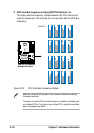
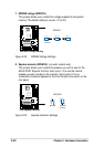
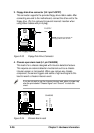
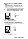
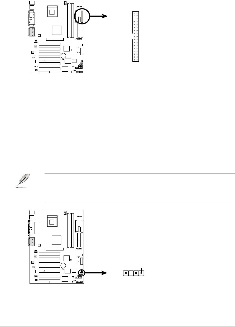
3. Floppy disk drive connector (34-1 pin FLOPPY)
This connector supports the provided floppy drive ribbon cable. After
connecting one end to the motherboard, connect the other end to the
floppy drive. (Pin 5 is removed to prevent incorrect insertion when
using ribbon cables with pin 5 plug).
Figure 2-33 Floppy Disk Drive Connector
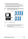
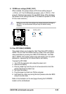
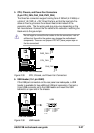
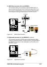
4. Chassis open alarm lead (4-1 pin CHASSIS)
This lead is for a chassis designed with intrusion detection feature.
This requires an external detection mechanism such as a chassis
intrusion sensor or microswitch. When you remove any chassis
component, the sensor triggers and sends a high-level signal to this
lead to record a chassis intrusion event.
Figure 2-34 Chassis Alarm Lead
If you do not wish to use the chassis intrusion lead, place a jumper cap
over the pins labeled “Chassis Signal” and “Ground” to close the
circuit.
P4B
®
NOTE: Orient the red markings on
the floppy ribbon cable to PIN 1.
P4B Floppy Disk Drive Connector
PIN 1
FLOPPY
P4B
®
P4B Chassis Alarm Lead
CHASSIS
+5VSB_MB
Chassis Signal
GND
1