


ASUS P4B266-E motherboard user guide
2-27
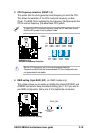
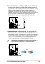
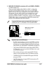
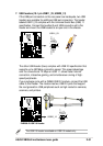
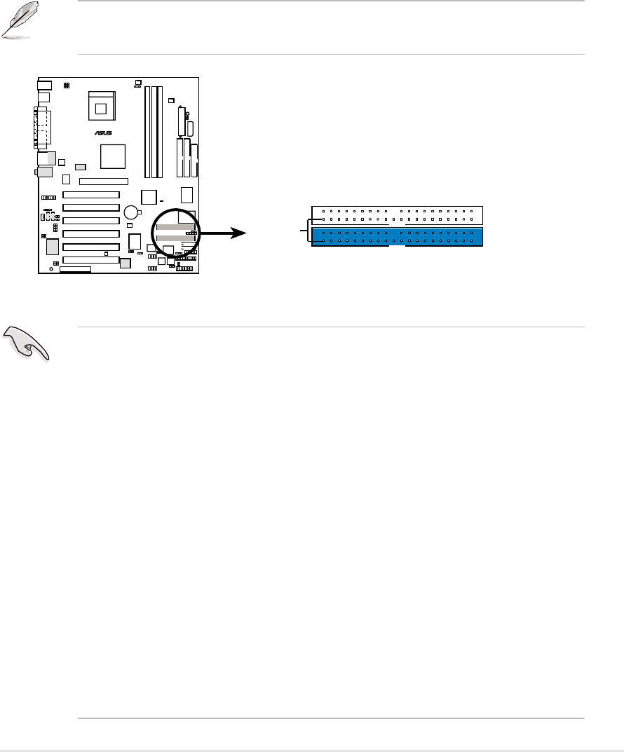
3. RAID ATA/133/100/66/33 connectors (40-1 pin ATAIDE1, ATAIDE2)
(on RAID models only)
These connectors support either RAID 0 or RAID 1 configuration
through the onboard RAID controller chip. You can use the RAID
feature to set up a disk array configuration and to support additional
IDE devices. You can install a total of four hard disks, two on each
connector. However, only two can function in a RAID. For a high
performance RAID 0 or RAID 1 configuration, always use two separate
ATAIDE ribbon cables, one for the primary RAID IDE connector and
another for the secondary RAID IDE connector.
To use the RAID feature, make sure that the RAID_SW jumper is
enabled (set to pins 1-2). See page 2-19 for the jumper location.
P4B266-E
®
NOTE: Orient the red markings
(usually zigzag) on the IDE
ribbon cable to PIN 1.
ATAIDE2
PIN 1
ATAIDE1
P4B266-E ATAIDE Connectors
Important notes on the RAID feature:
• By default, the drives that you connect to the ATAIDE connectors
follow the ATA133/100/66/33 protocol as independent drives, not
as a disk array. If you wish to configure the drives as a disk array,
refer to section “5.4 RAID 0/RAID 1 configurations” on page 5-18.
• The Promise
®
PDC20276 RAID chipset supports RAID 0/RAID 1
for Master drives only. You may connect one Master drive in each
of the ATAIDE connectors.
• When creating a disk array, use two separate ATA/133 ribbon
cables to connect two Master drives to the ATAIDE connectors.
• The MBFastTrak133 Lite’s bootable BIOS supports LBA 48-bit
drives over 137GB.
• The RAID chipset does not support ATAPI devices such as CD-
ROMs, DVD-ROMs, etc.