


ASUS P4B266-E motherboard user guide
2-37
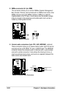
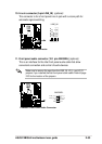
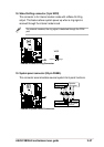
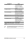
19. System panel connector (20-pin PANEL)
This connector accommodates several system front panel functions.
P4B266-E
®
P4B266-E System Panel Connectors
* Requires an ATX power supply.
PLED
Ground
MLED
PWR
+5 V
Keylock
+5V
Speaker
Speaker
Connector
Power LED
Ground
+5 V
Reset SW
SMI Lead
Message LED
ExtSMI#
Ground
Reset
Ground
Ground
Ground
Keyboard Lock
ATX Power
Switch*
P4B266-E
®
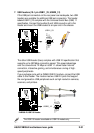
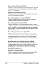
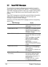
P4B266-E Wake-On-Ring Connector
WOR
Ring#Ground
21
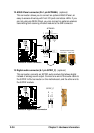
18. Wake-On-Ring connector (2-pin WOR)
This connector is for internal modem cards with a Wake-On-Ring
output. This feature allows system power up when a ring signal is
received through the internal modem card.
For external modems, the ring signal is detected through the COM
port.