


ASUS P4PE BP motherboard user guide
1-21
P4PE BP
®
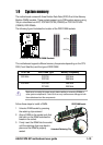
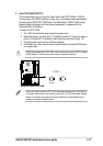
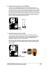
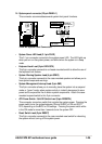
P4PE BP Chassis Alarm Lead
CHASSIS1
+5VSB_MB
Chassis Signal
GND
(Default)
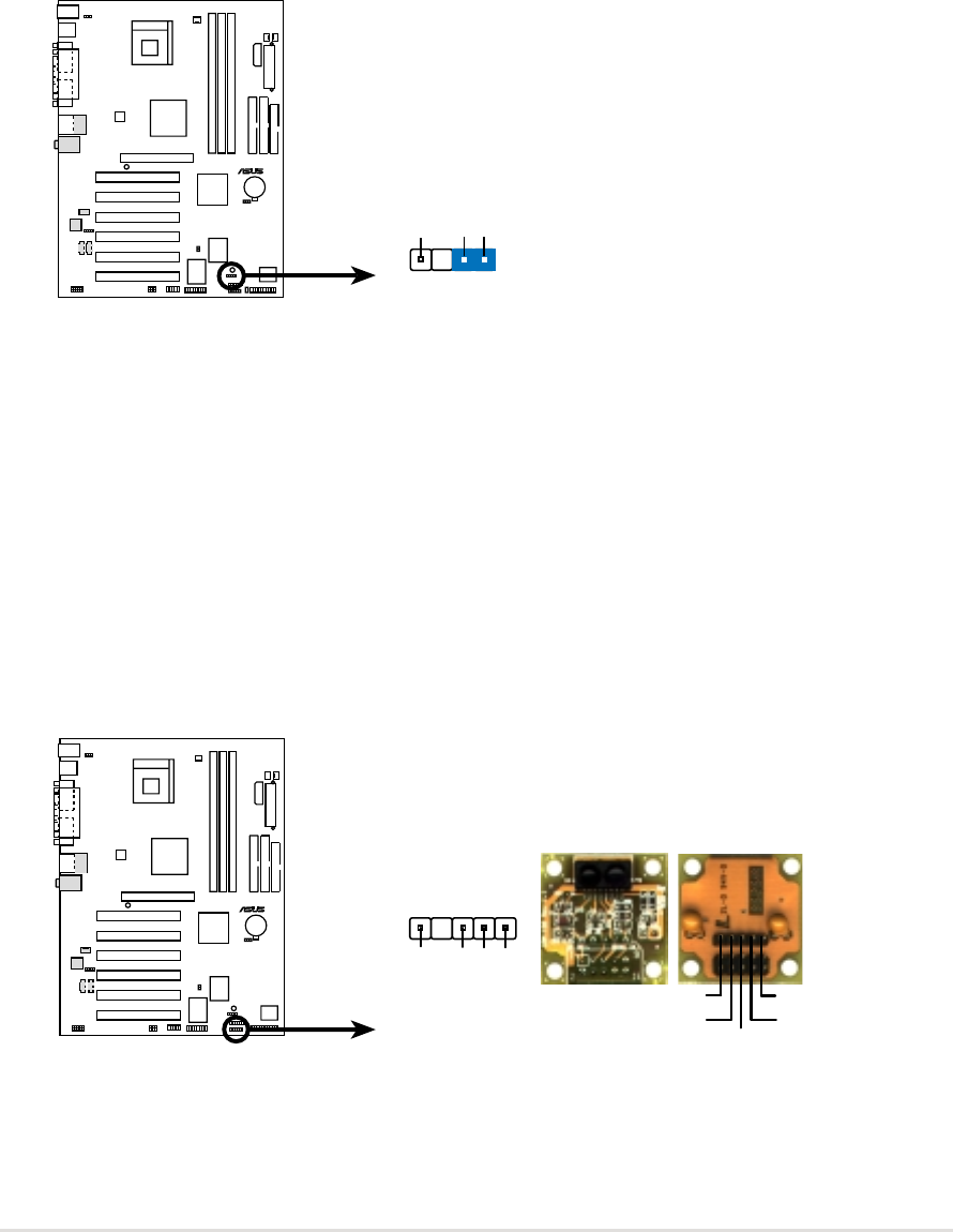
6. Chassis intrusion connector (4-1 pin CHASSIS1)
This lead is for a chassis designed with intrusion detection feature. This
requires an external detection mechanism such as a chassis intrusion sensor
or microswitch. When you remove any chassis component, the sensor triggers
and sends a high-level signal to this lead to record a chassis intrusion event.
By default, the pins labeled “Chassis Signal” and “Ground” are shorted
with a jumper cap. If you wish to use the chassis intrusion detection
feature, remove the jumper cap from the pins.
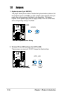
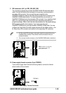
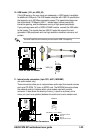
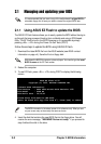
7. Infrared module connector (5-1 pin IR1)
This connector supports an optional wireless transmitting and receiving
infrared module. This module mounts to a small opening on system chassis
that support this feature. You must also configure the UART2 Use As
parameter in BIOS to set UART2 for use with IR.
Use the five pins as shown in Back View and connect a ribbon cable
from the module to the motherboard SIR connector according to the
pin definitions.
P4PE BP
®
P4PE BP Infrared Module Connector
Back View
+5V
IRTX
IRRX
(NC)
GND
Front View
IR1
+5V
IRRX
IRTX
GND
1