


32
Chapter 2: Hardware information
Some pins are used for connectors or power sources. These are
clearly distinguished from jumpers in the Motherboard Layout. Placing
jumper caps over these connector pins will cause damage to your
motherboard.
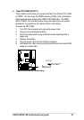
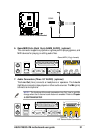
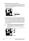
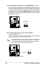
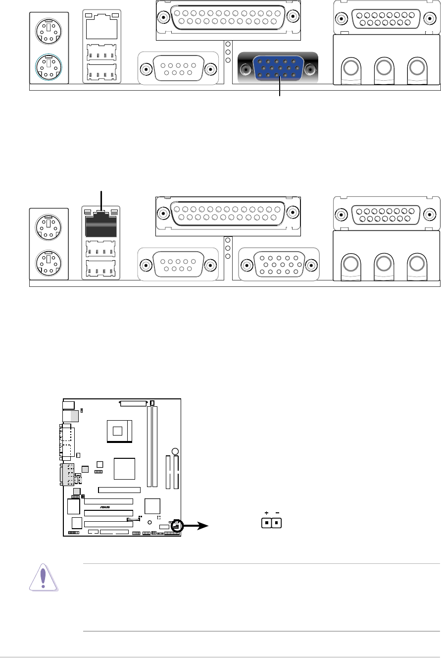
10. IDE Activity LED (2-pin IDELED)
This connector supplies power to the hard disk activity LED. The read or
write activities of any device connected to the primary or secondary IDE
connector cause this LED to light up.
P4S533-VM
®
P4S533-VM IDE Activity LED
TIP: If the case-mounted LED does not
light, try reversing the 2-pin plug.
IDE_LED1
RJ-45
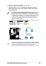
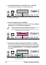
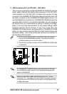
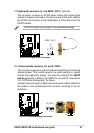
9. Fast-Ethernet Port Connector (RJ45) (optional)
This RJ45 connector is located on top of the USB Ports 0 & 1. The RJ45
supports connectivity for local area networks.
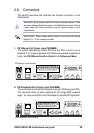
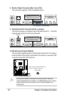
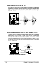
8. Monitor Output Connector (Blue 15 pin VGA)
This connector supports a VGA-compatible device.
VGA Monitor (15-pin female)