


ASUS P4S533-VM motherboard user guide
33
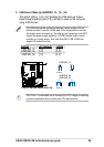
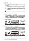
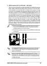
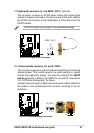
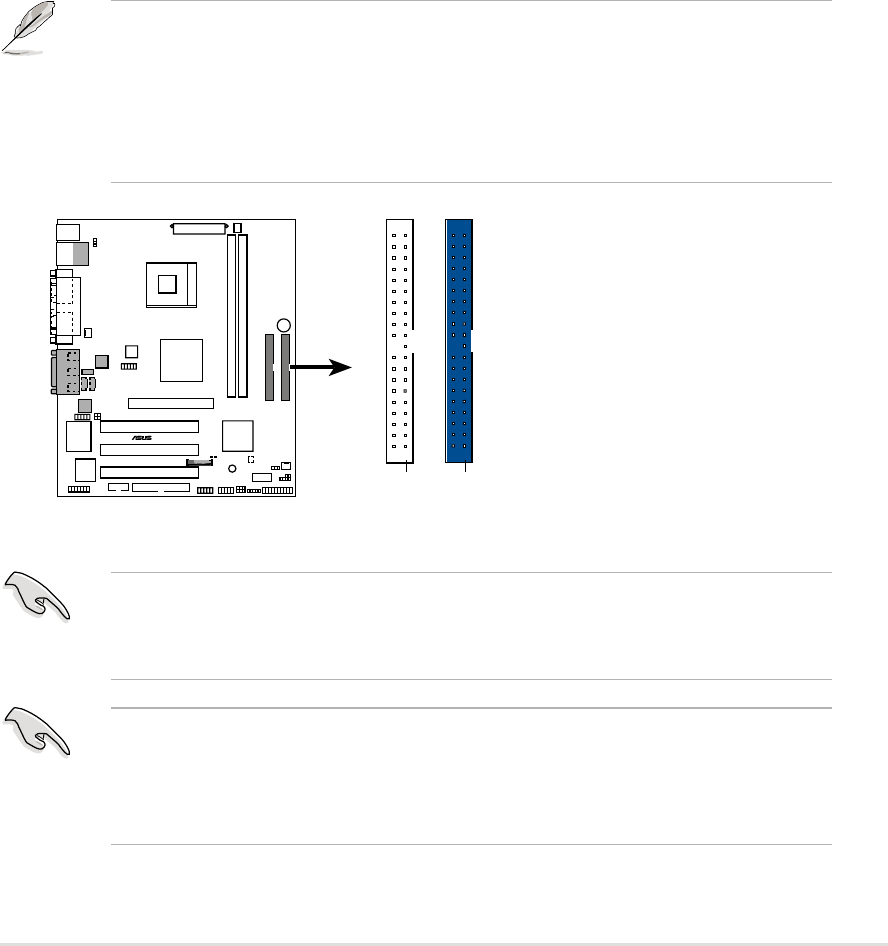
11. IDE Connectors (40-1 pin PRI_IDE1 / SEC_IDE1)
This connector supports the provided UltraDMA133/100/66 IDE hard disk
ribbon cable. Connect the cable’s blue connector to the PRI_IDE1
(recommended) or to the SEC_IDE1 connector; then connect the gray
connector to the UltraDMA133/100/66 slave device (hard disk drive) and
the black connector to the UltraDMA133/100/66 master device. It is
recommended that you connect non-UltraDMA133/100/66 devices to the
secondary IDE connector. If you install two hard disks, you must configure
the second drive as a slave device by setting its jumper accordingly.
Refer to the hard disk documentation for the jumper settings. BIOS
supports specific device bootup. If you have more than two
UltraDMA133/100/66 devices, purchase another UltraDMA133/100/66
cable. You may configure two hard disks to be both master devices with
two ribbon cables – one for the primary IDE connector and another for
the secondary IDE connector.
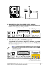
1. Pin 20 on each IDE connector is removed to match the covered
hole on the UltraDMA cable connector. This prevents incorrect
orientation when you connect the cables.
2. The hole near the blue connector on the UltraDMA133/100/66 cable
is intentional.
For UltraDMA133/100/66 IDE devices, use an 80-conductor IDE cable.
The UltraDMA/66 cable included in the motherboard package also
supports UltraDMA133.
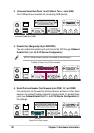
P4S533-VM
®
P4S533-VM IDE Connectors
NOTE: Orient the red markings
on the IDE ribbon cable to
PIN 1
SEC_IDE1
PIN 1
PRI_IDE1
PIN 1
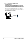
Always connect ribbon cables with the red stripe to Pin 1 on the
connectors. Pin 1 is usually on the side closest to the power connector
on hard drives and CD-ROM drives, but may be on the opposite side
on floppy disk drives.