


1-18
Chapter 1: Product introduction
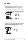
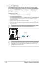
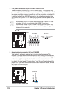
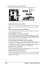
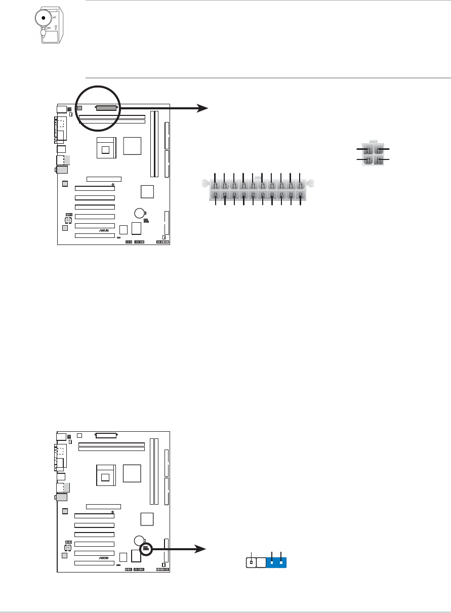
3. ATX power connectors (20-pin ATXPWR, 4-pin ATX12V)
These connectors connect to an ATX 12V power supply. The plugs from the
power supply are designed to fit these connectors in only one orientation. Find
the proper orientation and push down firmly until the connectors completely fit.
In addition to the 20-pin ATXPWR connector, this motherboard requires that
you connect the 4-pin ATX +12V power plug to provide sufficient power to the
CPU.
Make sure that your ATX 12V power supply can provide 8A on the +12V lead
and at least 1A on the +5-volt standby lead (+5VSB). The minimum
recommended wattage is 230W, or 300W for a fully configured system. The
system may become unstable and may experience difficulty powering up if the
power supply is inadequate.
P4SDX
®
P4SDX ATX Power Connector
ATXPWR ATX12V
+12V DC
GND
+12V D
C
GND
Pin 1
+3.3VDC
-12.0VDC
COM
PS_ON#
COM
COM
COM
-5.0VDC
+5.0VDC
+5.0VDC
PWR_OK
+12.0VDC
+3.3VDC
+3.3VDC
COM
+5.0VDC
COM
+5.0VDC
COM
+5VSB
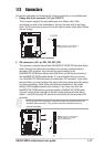
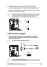
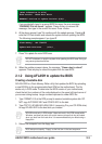
5. Chassis intrusion connector (4-1 pin CHASSIS)
This lead is for a chassis designed with intrusion detection feature. This
requires an external detection mechanism such as a chassis intrusion sensor
or microswitch. When you remove any chassis component, the sensor triggers
and sends a high-level signal to this lead to record a chassis intrusion event.
By default, the pins labeled “Chassis Signal” and “Ground” are shorted with a
jumper cap. If you wish to use the chassis intrusion detection feature, remove
the jumper cap from the pins.
P4SDX
®
P4SDX Chassis Alarm Lead
CHASSIS
+5VSB_MB
Chassis Signal
GND
(Defaul
t)