


ASUS P4T User’s Manual 39
3. HARDWARE SETUP
Connectors
3. H/W SETUP
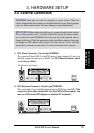
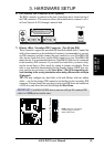
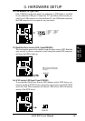
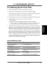
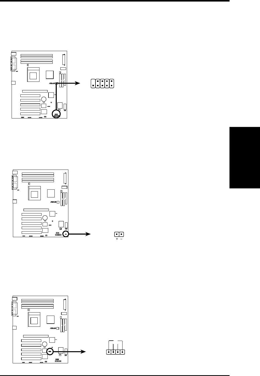
14) USB Headers (10-1 pin USB2)
If the USB Ports on the back panels are inadequate, a USB header is available
for two additional USB ports. Connect the 10-1 pin ribbon cable from the pro-
vided 2-port USB connector set to the midboard 10-1 pin USB header and mount
the USB connector set to an open slot on your chassis.
P4T
®
P4T USB Headers
USB2
15
610
1: USB Power
2: USBP2–
3: USBP2+
4: GND
5: NC
6: USB Power
7: USBP3–
8: USBP3+
9: GND
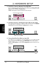
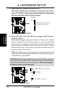
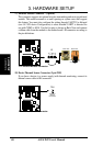
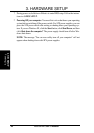
15) Hard Disk Drive Activity LED (2-pin HDDLED)
This lead supplies power to the cabinet’s hard disk drive activity LED. Read and
write activity by devices connected to the Primary/Secondary IDE connectors
will cause the LED to light up.
P4T Hard Disk Drive Activity LED
TIP: If the case-mounted LED
does not light, try reversing the
2-pin plug.
HDDLED
P4T
®
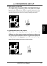
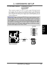
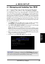
16) SCSI Activity LED Lead (2-pin SCSILED)
To use the Hard Disk Drive Activity LED indicator with a SCSI device con-
nected to an add-in PCI SCSI card, connect the 4-pin connector on the PCI SCSI
card to this lead. When connected, the cabinet’s IDE activity LED will indicate
activity of the SCSI device.
+
1
P4T SCSI LED Connector
SCSILED
P4T
®
-