


40 ASUS P4T User’s Manual
Connectors
3. H/W SETUP
3. HARDWARE SETUP
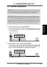
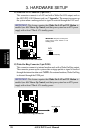
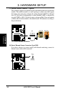
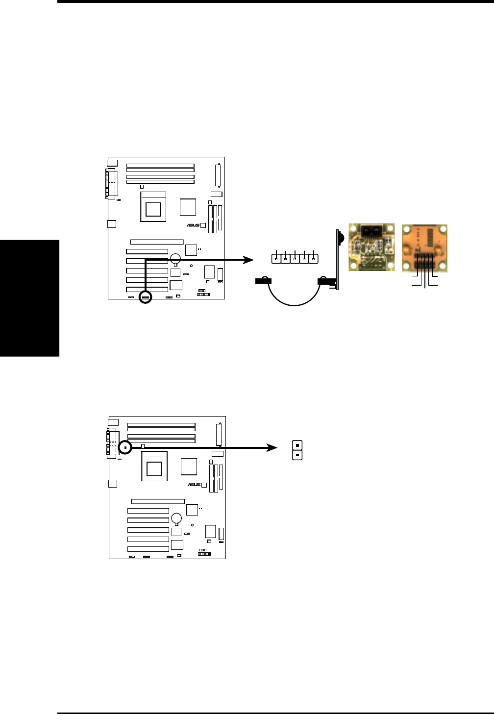
17) Infrared Module Connector (5-pin IR)
This connector supports an optional wireless transmitting and receiving infrared
module. This module mounts to a small opening on system cases that support
this feature. You must also configure the setting through UART2 Use Infrared
(see 4.4.2 I/O device Configuration) to select whether UART2 is directed for
use with COM2 or IrDA. Use the five pins as shown in Back View and connect
a ribben cable from the module to the motherboard’s IR connector according to
the pin definitions.
Front View Back View
+5V
IRTX
IRRX
(NC)
GND
+5V
IRRX
IRTX
(NC)
GND
IR
1
P4T Infrared Module Connector
P4T
®
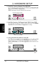
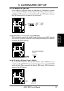
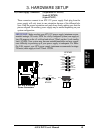
18) Device Thermal Sensor Connector (2-pin TR2)
If you have a device (e.g. power supply) with thermal monitoring, connect its
thermal sensor cable to this connector.
P4T Thermal Sensor Connector
P4T
®
TR2
Thermal
Sensor
Connector