


38 ASUS P4T-E User’s Manual
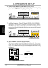
Connectors
3. H/W SETUP
3. HARDWARE SETUP
P4T-E
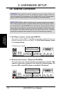
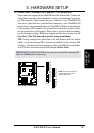
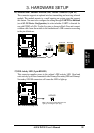
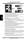
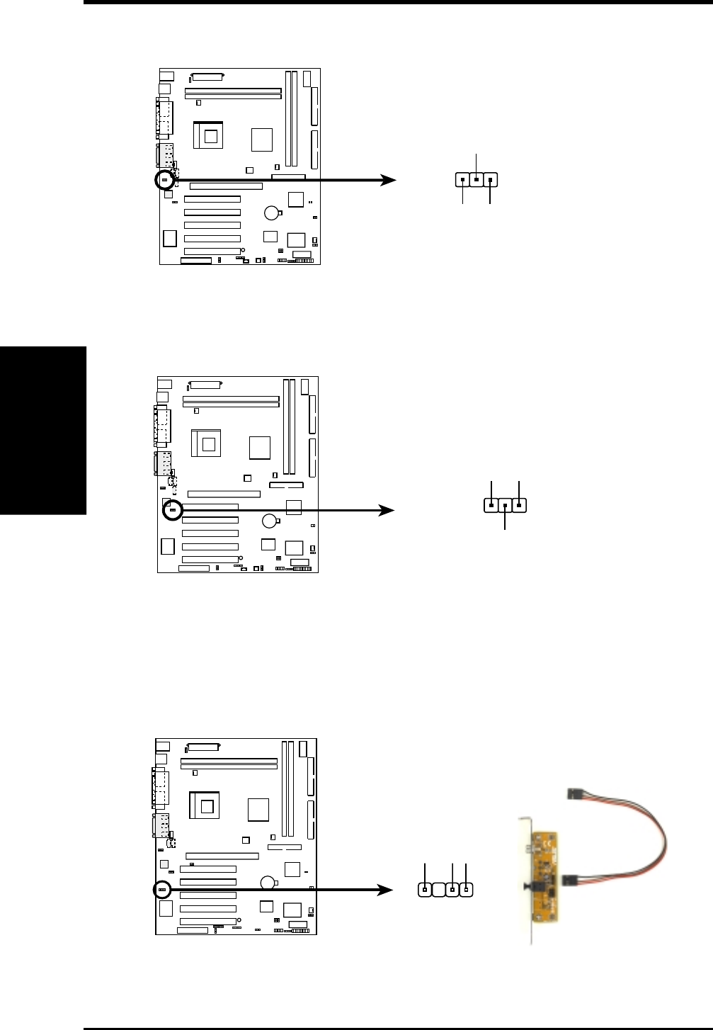
P4T-E True-Level Line Out Header
HEADPHONE
1
Headphone Left
GND
Headphone Right
P4T-E
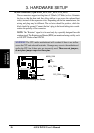
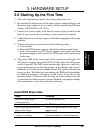
P4T-E Internal Microphone Connector
MIC2
MIC Power
1
MIC Input
Ground
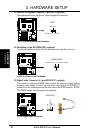
13) Internal Microphone Connector (3 pin MIC2) (optional)
Microphone audio may be directly input through this connector.
14) Headphone (3 pin HEADPHONE) (optional)
An external headphone feeds from the motherboard using this connector.
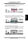
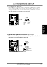
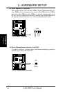
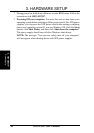
15) Digital Audio Connector (4-1 pin SPDIFOUT) (optional)
This connector supports an SPDIF audio module that processes digital instead
of analog audio output. Connect one end of the audio cable to the SPDIFOUT
connector on the motherboard and the other end to the SPDIF module. NOTE:
The SPDIF module must be purchased separately.
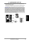
P4T-E
P4T-E Digital Audio Connector
+5V
SPDIFOUT
GND
SPDIFOUT