


ASUS P4V800-X motherboard user guide
1-23
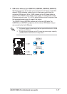
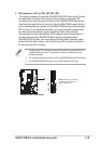
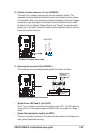
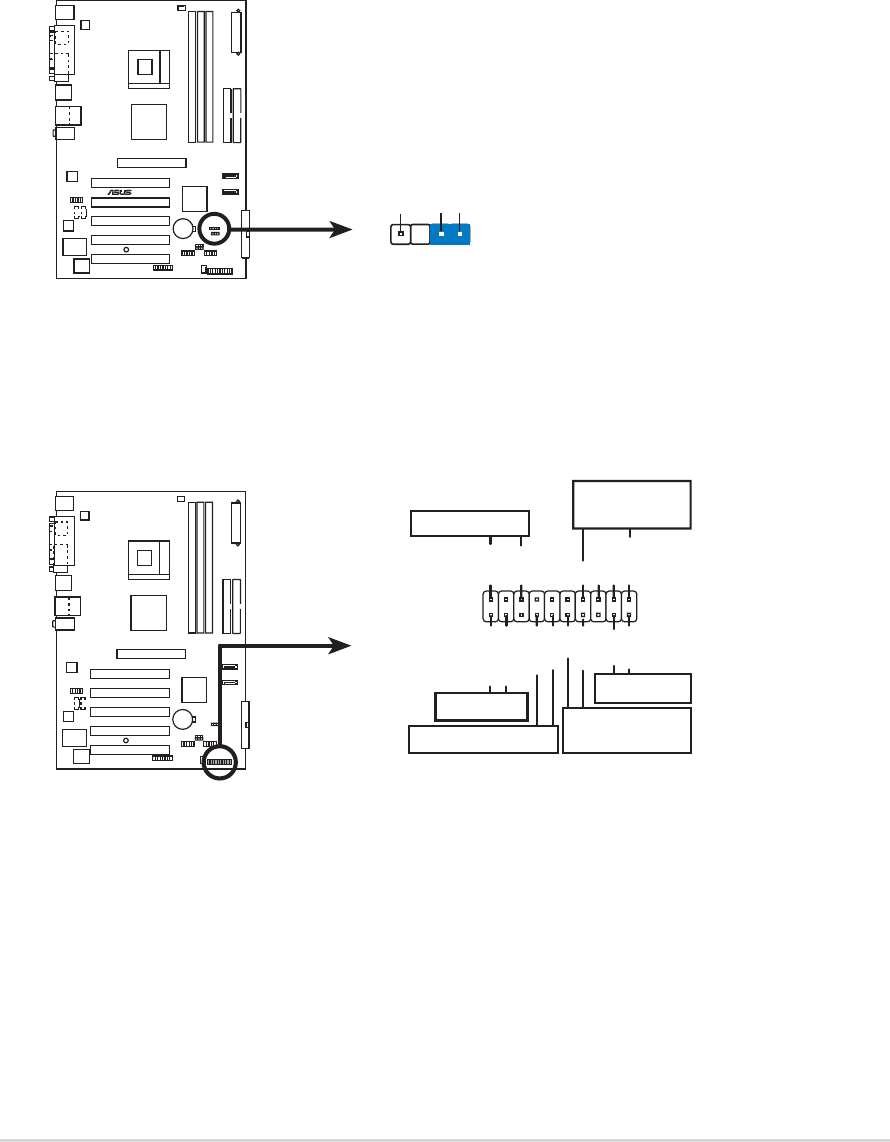
10. Chassis intrusion connector (4-1 pin CHASSIS1)
This lead is for a chassis designed with intrusion detection feature. This
requires an external detection mechanism such as a chassis intrusion sensor
or microswitch. When you remove any chassis component, the sensor triggers
and sends a high-level signal to this lead to record a chassis intrusion event.
By default, the pins labeled “Chassis Signal” and “Ground” are shorted with a
jumper cap. If you wish to use the chassis intrusion detection feature, remove
the jumper cap from the pins.
P4V800-X
®
P4V800-X Chassis Alarm Lead
CHASSIS
1
+5VSB_MB
Chassis Signal
GND
(Defaul
t)
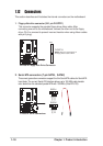
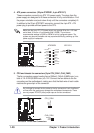
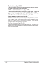
11. System panel connector (20-pin PANEL1)
This connector accommodates several system front panel functions.
P4V800-X
P4V800-X System Panel Connector
* Requires an ATX power supply
.
PLED-
Ground
PWR
+5V
Speaker
Speaker
Connector
Power LED
Ground
Reset SW
SMI Lead
ExtSMI#
Ground
Reset
Ground
Ground
ATX Power
Switch*
PLED+
IDE_LED-
IDE_LED+
IDE_LED
• System Power LED Lead (3-1 pin PLED)
This 3-1 pin connector connects to the system power LED. The LED lights up
when you turn on the system power, and blinks when the system is in sleep
mode.
• System Warning Speaker Lead (4-pin SPKR)
This 4-pin connector connects to the case-mounted speaker and allows you to
hear system beeps and warnings.