


2-262-26
2-262-26
2-26
Chapter 2: Hardware informationChapter 2: Hardware information
Chapter 2: Hardware informationChapter 2: Hardware information
Chapter 2: Hardware information
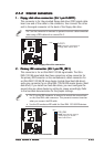
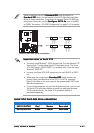
• Before creating a RAID set using Ultra ATA hard disks, make sure
that you have connected the Ultra ATA signal cable and installed Ultra
ATA 133/100/66 hard disk drives.
• The system automatically assigns the boot sequence of ATAPI
devices connected to the IDE RAID connectors.
• The ITE
®
8212F controller supports a maximum of two Ultra ATA
hard disk drives in RAID 1 configuration.
• Before creating a RAID 1 set, make sure that you set the hard disk
drives as either Master or Slave device. Refer to the hard disk drive
documentation for details.
3.3.
3.3.
3.
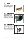
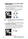
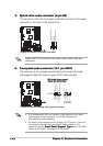
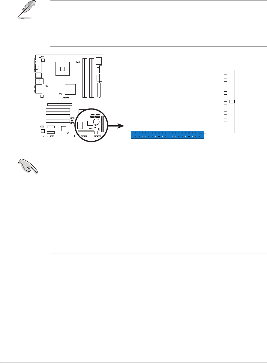
IDE RAID connectors (40-1 pin PRI_RAID1 [red],IDE RAID connectors (40-1 pin PRI_RAID1 [red],
IDE RAID connectors (40-1 pin PRI_RAID1 [red],IDE RAID connectors (40-1 pin PRI_RAID1 [red],
IDE RAID connectors (40-1 pin PRI_RAID1 [red],
SEC_RAID1 [red])SEC_RAID1 [red])
SEC_RAID1 [red])SEC_RAID1 [red])
SEC_RAID1 [red])
These connectors are for Ultra ATA 133/100/66 signal cables. The
IDE RAID connectors support up to four IDE hard disk drives that you
can configure as a disk array through the onboard IDE RAID controller.
Refer to Chapter 5 for details on how to set up RAID configurations.
These connectors are set to
IDE IDE
IDE IDE
IDE
MM
MM
M
ode ode
ode ode
ode by default. In
IDE IDE
IDE IDE
IDE
MM
MM
M
odeode
odeode
o d e, you
can connect IDE devices to these connectors such as boot/data hard disk
drives or optical drives. If you intend to create an IDE RAID set using these
connectors, set the
ITE8212F ControllerITE8212F Controller
ITE8212F ControllerITE8212F Controller
ITE8212F Controller item in the BIOS to [RAID
Mode]. See section “4.4.6 Onboard Devices Configuration” for details.
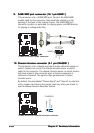
P5AD2-E
DELUXE
®
P5AD2-E DELUXE RAID connectors
NOTE: Orient the red markings
(usually zigzag) on the IDE
cable to PIN 1.
PRI_RAID1
PIN 1
SEC_RAID1
4.4.
4.4.
4.
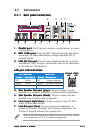
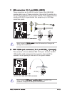
Serial ATA connectors (7-pin SATA1 [red], SATA2 [red],Serial ATA connectors (7-pin SATA1 [red], SATA2 [red],
Serial ATA connectors (7-pin SATA1 [red], SATA2 [red],Serial ATA connectors (7-pin SATA1 [red], SATA2 [red],
Serial ATA connectors (7-pin SATA1 [red], SATA2 [red],
SATA3 [black], SATA4 [black])SATA3 [black], SATA4 [black])
SATA3 [black], SATA4 [black])SATA3 [black], SATA4 [black])
SATA3 [black], SATA4 [black])
These connectors are for the Serial ATA signal cables for Serial ATA
hard disk drives.
If you installed Serial ATA hard disk drives, you can create a RAID 0 or
RAID 1 configuration with the Intel
®
Matrix Storage Technology
through the onboard Intel
®
ICH6R RAID controller. Refer to Chapter 5
for details on how to set up Serial ATA RAID configurations.