


1-32 Chapter 1: Product introduction
1.10.2 Internal connectors
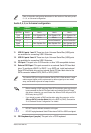
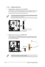
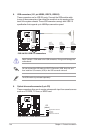
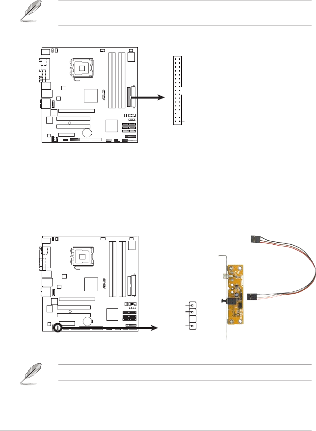
1. Floppy disk drive connector (34-1 pin FLOPPY)
This connector is for the provided oppy disk drive (FDD) signal cable. Insert
one end of the cable to this connector, then connect the other end to the
signal connector at the back of the oppy disk drive.
Pin 5 on the connector is removed to prevent incorrect cable connection when
using a FDD cable with a covered Pin 5.
R
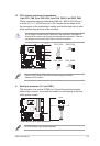
P5B-VM DO
Floppy Disk Drive Connector
PIN 1
NOTE:
Orient the red markings on
the floppy ribbon cable to PIN 1.
FLOPPY
P5B-VM DO
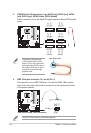
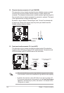
2. Digital Audio connector (4-1 pin SPDIF_OUT)
This connector is for the S/PDIF audio module to allow digital sound output.
Connect one end of the S/PDIF audio cable to this connector and the other
end to the S/PDIF module.
The S/PDIF out module is purchased separately.
R
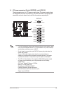
SPDIF_OUT
+5V
Spdif out
GND
P5B-VM DO
P5B-VM DO SPDIF OUT connector