


1-61-6
1-61-6
1-6
Chapter 1: Product introductionChapter 1: Product introduction
Chapter 1: Product introductionChapter 1: Product introduction
Chapter 1: Product introduction
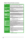
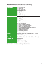
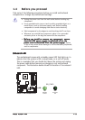
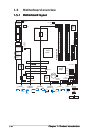
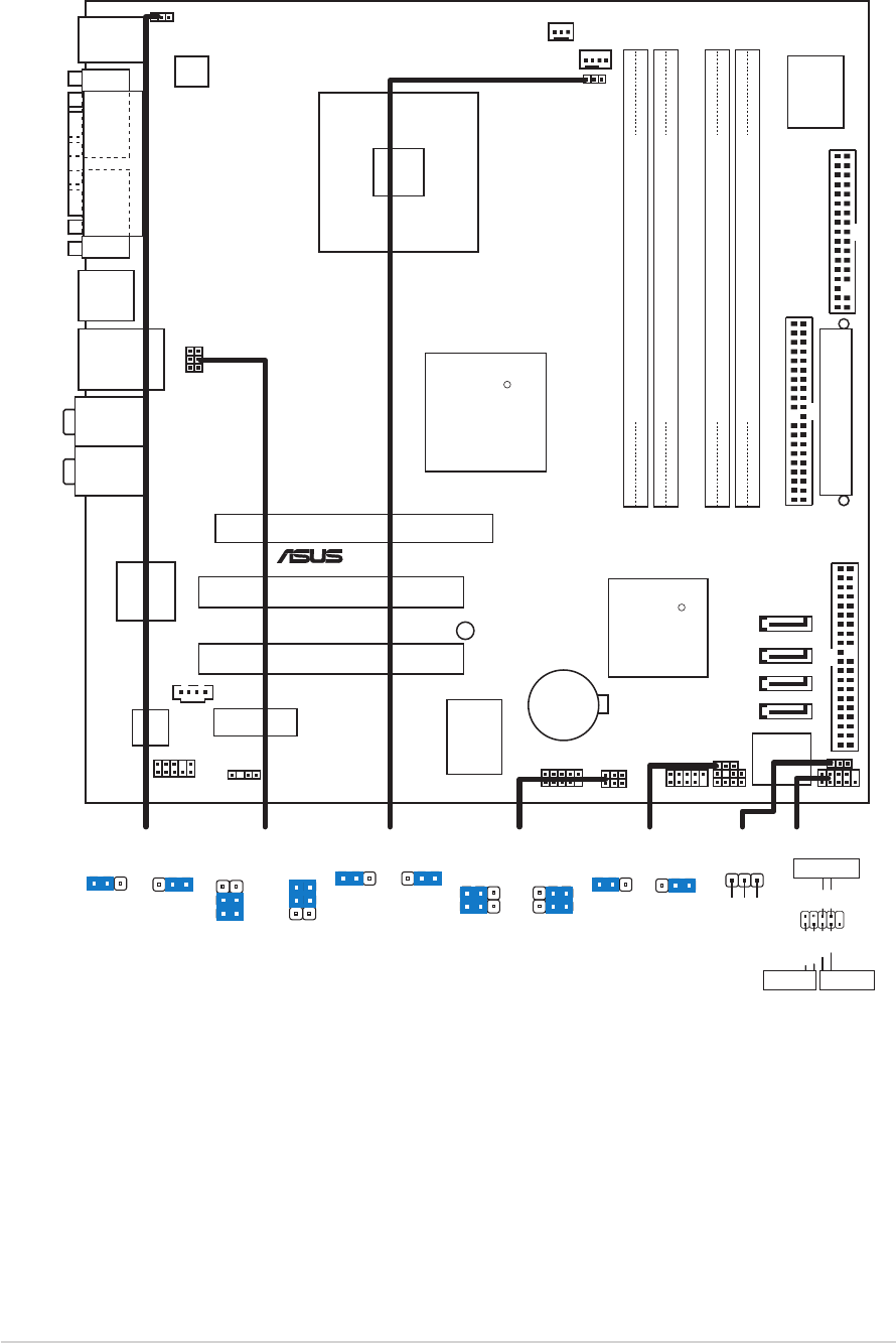
1.5 Motherboard overview
1.5.11.5.1
1.5.11.5.1
1.5.1
Motherboard layoutMotherboard layout
Motherboard layoutMotherboard layout
Motherboard layout
3
2
21
Below:
Center/Subwoofer
Center:
Side Speaker Out
Top:Rear Speaker Out
+5V
(Default)
+5VSB
USBPW56
USBPW78
(Default)
+5V +5VSB
KBPWR1
2312
CLRTC1
Normal Clear CMOS
(Default)
12 23
P5GD1-VM
CR2032 3V
Lithium Cell
CMOS Power
CD1
Super
I/O
Intel FWH
4Mb
ATX12V1
FLOPPY1
AAFP1
DDR DIMM_A1 (64 bit,240-pin module)
KBPWR1
SB_PWR1
USBPW34
USBPW12
F_PANEL1
CHASSIS1USB78
USB56
USBPW56
USBPW78
PRI_PCIIDE1
CLRTC1
SATA1
PCI1
Intel
915G
Intel
ICH6
DDR DIMM_A2 (64 bit,240-pin module)
DDR DIMM_B1 (64 bit,240-pin module)
DDR DIMM_B2 (64 bit,240-pin module)
CHA_FAN1
CPU_FAN1
PRI_IDE1
ITE
8211
ALC880
EATXPWR1
SATA3
SATA2
SATA4
PCI2
SPDIF_OUT1
Kinnereth
82562EZ
R
LGA775
PS/2KBMS
T: Mouse
B: Keyboard
Below:Mic In
Center:Line Out
Top:Line In
F_USB12
LAN_USB34
PCIEX1_1
PCIEX16
COM1
PARALLEL PORT
VGA1
SPEAKER1
PLED1
R
®
USBPW12
USBPW34
3
2
2
1
+5V
(Default)
+5VSB
F_PANEL1
*
Requires an ATX power supply
.
PWR
Ground
GNDReset
IDE_LED+
IDE_LED-
RESET
IDE LED
PWRSW
FANPWR1
PLED1
PLED+
1
NC
PLED-
FANPWR1
DC modePWM
(Default)
12
23