


1-341-34
1-341-34
1-34
Chapter 1: Product introductionChapter 1: Product introduction
Chapter 1: Product introductionChapter 1: Product introduction
Chapter 1: Product introduction
•
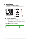
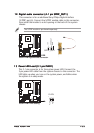
Hard disk drive activity LED (Red 2-pin IDELED)Hard disk drive activity LED (Red 2-pin IDELED)
Hard disk drive activity LED (Red 2-pin IDELED)Hard disk drive activity LED (Red 2-pin IDELED)
Hard disk drive activity LED (Red 2-pin IDELED)
This 2-pin connector is for the HDD Activity LED. Connect the HDD
Activity LED cable to this connector. The IDE LED lights up or flashes
when data is read from or written to the HDD.
•
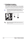
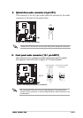
ATX power button/soft-off button (Yellow 2-pin PWRSW)ATX power button/soft-off button (Yellow 2-pin PWRSW)
ATX power button/soft-off button (Yellow 2-pin PWRSW)ATX power button/soft-off button (Yellow 2-pin PWRSW)
ATX power button/soft-off button (Yellow 2-pin PWRSW)
This connector is for the system power button. Pressing the power
button turns the system on or puts the system in sleep or soft-off
mode depending on the BIOS settings. Pressing the power switch for
more than four seconds while the system is ON turns the system OFF.
•
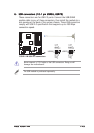
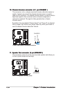
Reset button (Blue 2-pin RESET)Reset button (Blue 2-pin RESET)
Reset button (Blue 2-pin RESET)Reset button (Blue 2-pin RESET)
Reset button (Blue 2-pin RESET)
This 2-pin connector is for the chassis-mounted reset button for
system reboot without turning off the system power.
14.14.
14.14.
14.
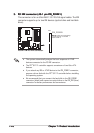
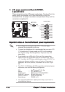
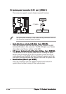
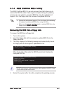
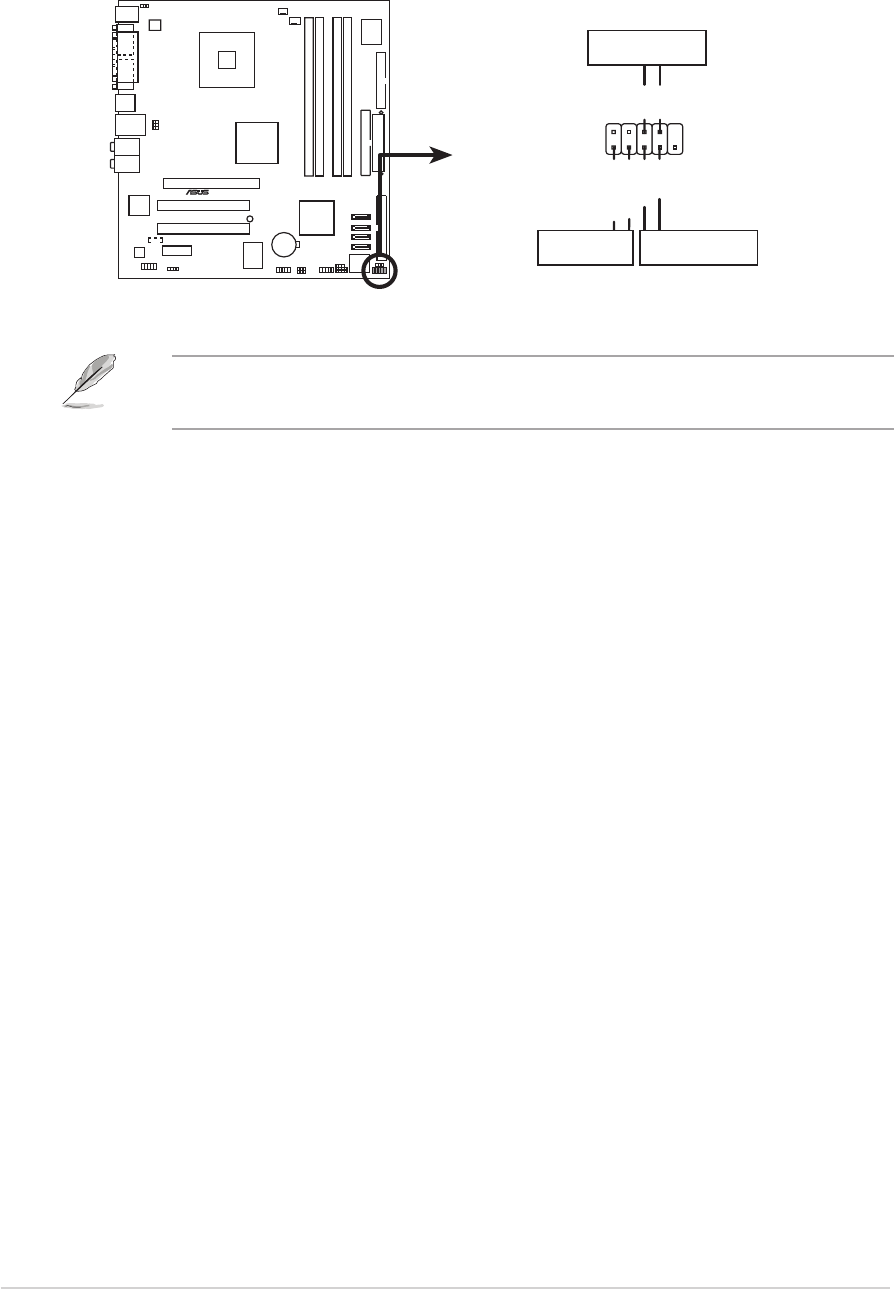
System panel connector (10-1 pin F_PANEL1)System panel connector (10-1 pin F_PANEL1)
System panel connector (10-1 pin F_PANEL1)System panel connector (10-1 pin F_PANEL1)
System panel connector (10-1 pin F_PANEL1)
This connector supports several chassis-mounted functions.
The sytem panel connector is color-coded for easy connection. Refer to
the connector description below for details.
P5GD1-VM
®
F_PANEL1
P5GD1-VM System panel connector
* Requires an ATX power supply
.
PWRGround
GNDReset
IDE_LED+
IDE_LED-
RESETIDE LED
PWRSW