


18 ASUS P/I-P55T2P4S User’s Manual
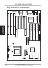
III. INSTALLATION
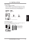
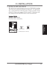
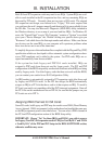
2. System Memory (DRAM & SRAM)
This motherboard supports six 72-pin SIMMs of 4MB, 8MB, 16MB, 32MB, or
64MB to form a memory size between 8MB to 256MB. The DRAM can be either
60ns or 70ns Fast Page Mode (Asymmetric or Symmetric) or EDO. To support
ECC, you must use true (opposed to phantom parity generated by logic chips) 36-bit
parity-type DRAM (e.g. 8 chips + 4 parity chips) in pairs for all modules. Mixing
32-bit non-parity DRAM (e.g. 8 chips) and 36-bit DRAM (e.g. 12 chips) will work
minus the ECC feature.
III. INSTALLATION
(Memory)
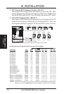
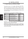
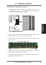
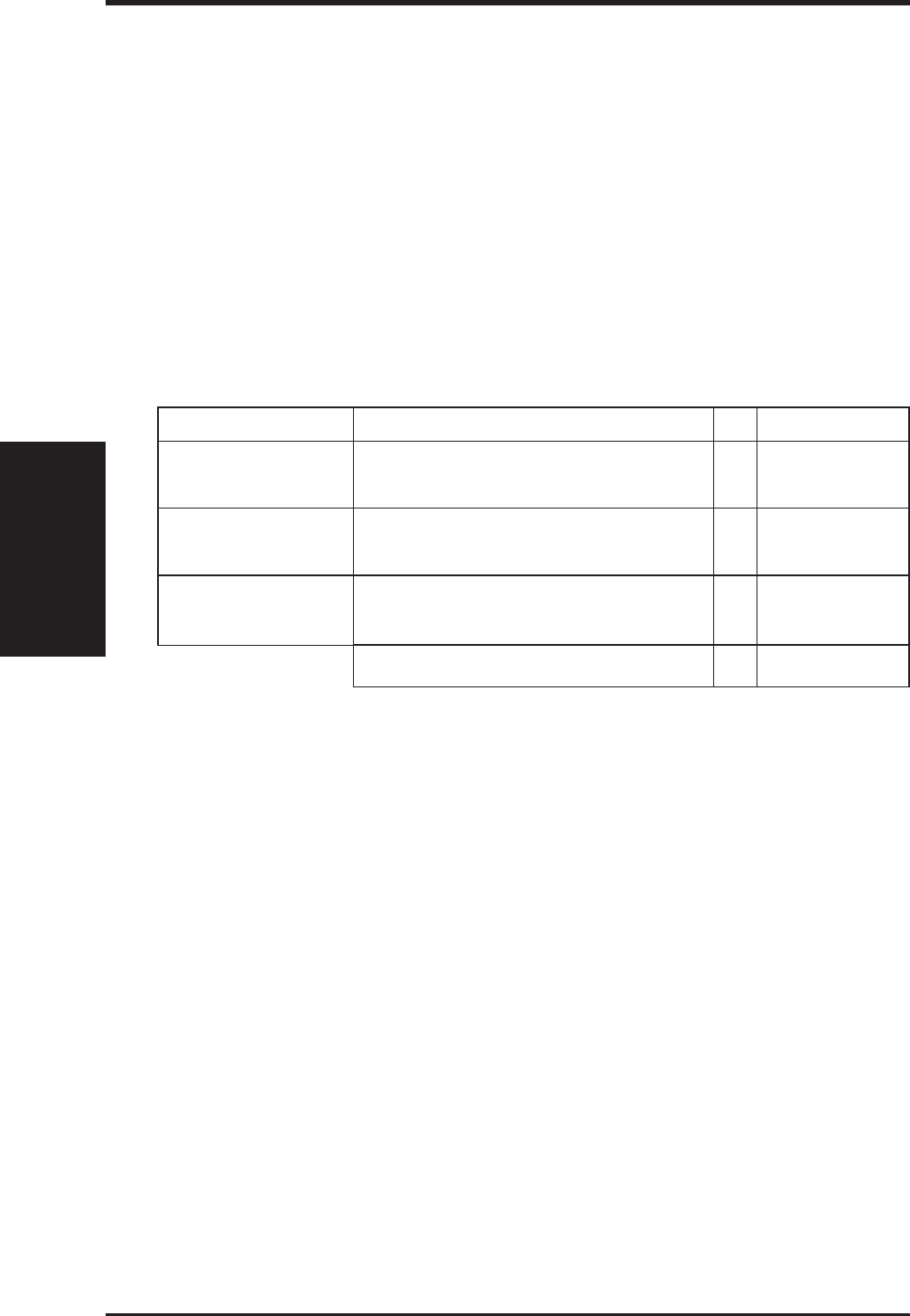
Install memory in any or all of the banks in any combination as follows:
Bank Memory Module Total Memory
Bank 0 4MB, 8MB, 16MB, 32MB, 64MB x2
SIMM Sockets 1&2 72-pin FPM, EDO SIMM
Bank 1 4MB, 8MB, 16MB, 32MB, 64MB x2
SIMM Sockets 3&4 72-pin FPM, EDO SIMM
Bank 2 4MB, 8MB, 16MB, 32MB, 64MB x2
SIMM Sockets 5&6 72-pin FPM, EDO SIMM
Total System Memory (384MB Max) =
IMPORTANT: Memory setup is required using “Auto Configuration" in
Chipset Features Setup of the BIOS SOFTWARE.
IMPORTANT: Each bank must have the same size memory installed in pairs.
Do not use memory modules with more than 24 chips per module. Modules
with more than 24 chips exceed the design specifications of the memory sub-
system and will be unstable.