


ASUS P/I-P55T2P4S User’s Manual 19
III. INSTALLATION
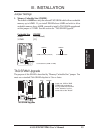
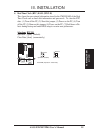
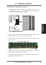
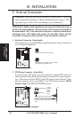
DRAM Memory Installation Procedures:
1. The SIMM memory modules will only fit in one orientation as shown because
of a "Plastic Safety Tab" on one end of the SIMM sockets which requires the
"Notched End" of the SIMM memory modules.
72 Pin SIMM DRAM Sockets
123456
Bank0Bank1Bank2
Notched End
72-Pin DRAM Modules
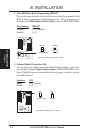
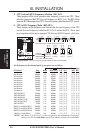
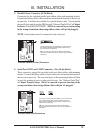
2. Press the memory module firmly into place starting from a 45 degree angle
making sure that all the contacts are aligned with the socket.
3. With your finger tips, rock the memory module into a vertical position so that it
clicks into place.
72 Pin DRAM in SIMM Socket
Support Clip
Safety Tab (This Side Only)
Mounting Hole
4. The plastic guides should go through the two "Mounting Holes" on the sides and
the "Metal Clips" should snap on the other side.
5. To release the memory module, squeeze both "Metal Clips" outwards and rock
the module out of the "Metal Clips".
(DRAM Memory)
III. INSTALLATION