


4 ASUS P/I-XP65NP5 User’s Manual
III. INSTALLATION
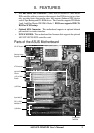
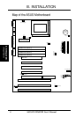
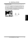
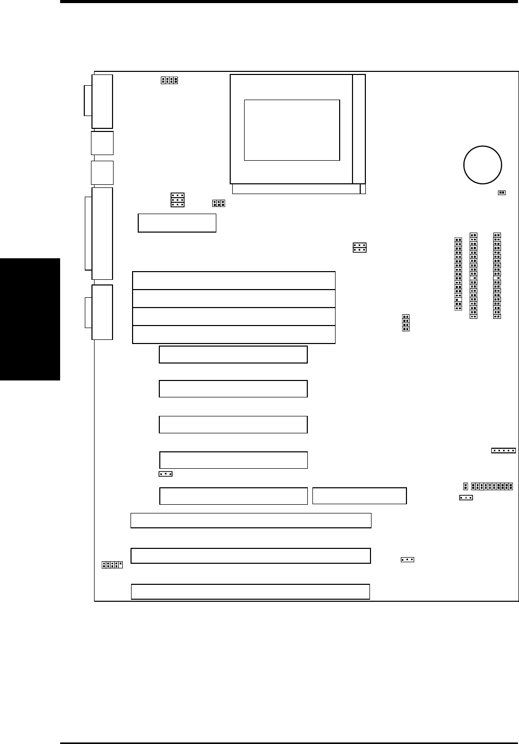
Map of the ASUS Motherboard
(Map of Board)
III. INSTALLATION
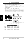
ISA Slot 2
ISA Slot 1
PCI Slot 5
PCI Slot 3
PCI Slot 2
PCI Slot 1
SIMM
Socket 1 (Bank 0)
SIMM
Socket 2 (Bank 0)
ISA Slot
3
SIMM Socket 3 (Bank 1)
SIMM
Socket 4 (Bank 1)
Board Power Input
for ATX Power Supply
JP8
JP9
PCI Slot 4
CPU ZIF Socket 8
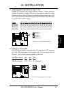
COM 2 Parallel Printer
PS/2
Mouse
PS/2
Key-
board
COM 1
JP6
Reg/ATX 3.3V
BUS Freq.
12V Fan Power
JP14
Multi-I/O Enable/Disable
Secondary IDE
Primary IDE
Floppy Drives
#CR2032
3Volt Button
Cell Battery
MediaBus 2.0
Case Connector
JP10
JP11
JP12
JP13
Freq. Ratio
CPU Voltage ID
JP1
JP2
JP3
JP4
Universal Serial Bus
(Reserved)
JP17
ROM Program (Dis/En)
JP16
CMOS (Clear/Operate)
IDE LED
Infrared Connector
JP7
Battery Test Lead